Sunrise lamp add-on for nixie alarm clock.

IMG_0848Finnish winter days are dark and cold. The sun rises only for short moment, and even then it is often cloudy, or the sun is so low that it can rarely be seen. A circadian clock is synchronized with daylight changes, and so without external stimulus from sunlight, my daily rhythm started to lag and spin around. Waking at morning was difficult task.

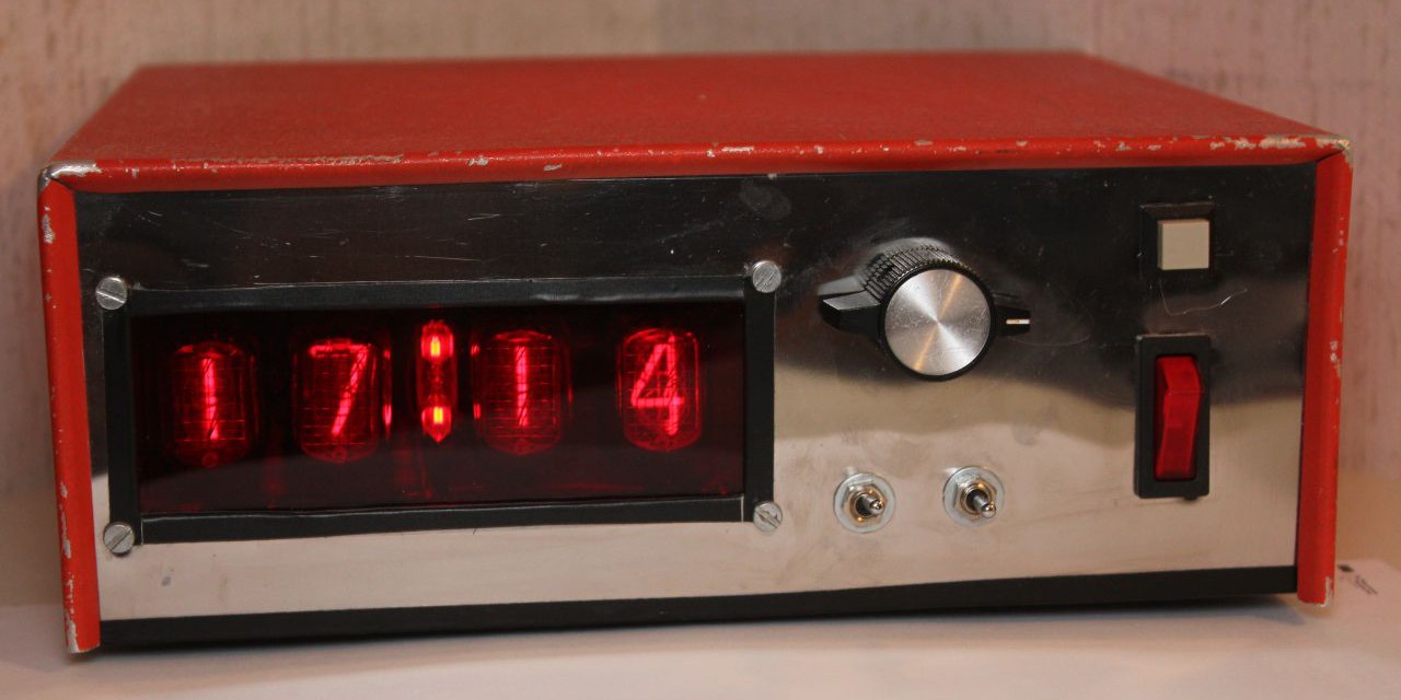
There is a ready-made solution for this, e.g. Philips does sell alarm clocks with build in wake-up lamps, that turn on at morning to artificially sync humans internal clock. Me being hacker, I had to make my own solution, as usual. Read More …

Nixie clock firmware

Firmware for clock is in publishable condition at last. Now all major functions are implemented and no bugs are (yet) found. But there will be likely future versions with slight fixes and features. And yes, it is made with basic, terrible, horrible and not 1337 at all, but  it was easier and I could ask help from friend who have similarly constructed clock. There is also slight chance that I will translate this to avr gcc, but it would be big job, because it have not all functions and stuff. Read More …

Nixie-clock update

Itty Bitty Buck converter

Everybody knows old 78xx linear regulators. They are ok for many applications, but are problematic for bigger currents. They drop and regulate voltage smoothly for circuitry, but because all excess voltage are dissipate as heat, they are very inefficient. For my nixie clock I needed efficient little power supply for 5V rail, so I created this little baby:

Look how cute it is!

Read More …

I feel so stupid ಠ_ಠ

Now I know why I2C was not working in my nixie clock. Today I got an arduino nano from helsinki hacklab, and started to troubleshoot my circuit. Oddly RTC worked when I tried it in breadboard, and also in clock’s motherboard, when nothing else were connected. Also noticed that when nixie driverboard was connected, both of the i2c lines had weird resistance to 5v and ground. I once again removed driver board from case and measured. It was ok, of course. I didn’t even tough about cabling <.< Read More …

Crimping connectors and waiting blue smoke

After a full day of work I have the electronics for the clock complete, or so I hope. And not a day without accidents; I spilled some Earl Grey to my Thinkpad T42’s keyboard, and now the m-letter is not working: I had to remap it to dead acute button. Now I need to get 300€ to buy thinkpad X60/x61(my X40 has a dead southbridge and writing with T42 without proper m-letter is very annoying). But back to the project.

Now I have the internals of the clock nearly finished. I fastened a mainboard to the bottom of the case because didn’t find the same L-mounts I used with the nixie control board. I also made a little board for the nixie psu. 

The mainboard is on the left. I originally wanted to install it the same way as control board but decided then screw it up to bottom of the case with spacers because this way it’s much more accessible. I positioned 170v psu to the bottom right corner with it’s own board in order to avoid shorts and interfere. Previously I somehow sorted 170v to 5v and burned all but russian K155ID1 IC’s. Soviet quality ;)

I am still waiting for a new atmega 16 (because the one in board seems to be broken too), and new usbasp programmer.

Mainboard for nixie clock and burned fingers

Finally I got time to continue the nixie clock. This week is the annual autumn break so hopefully I can make most parts of the clock ready. Writing program code is so time consuming that it is necessary to leave it for a later time. Yesterday I started to assemble the mainboard  for the clock. It went mostly without any problems (I dropped my N900 phone which broke down and burned my fingers as usual), and I finished it tonight.

Read More …