A Nixie tube is an electronic device for displaying numerals or other information. It is a cold-cathode tube and similar to a neon-lamp. Applying power to one cathode surrounds it with an orange glow discharge.
I started to build the nixie tube clock at the beginning of the 2012. I have had the idea for some time, but I did not have any nixies back then. I also didn’t have the required know-how to make circuits and boards for a clock. The idea became reality when my friend started to make his own clock.

Together we ordered some Russian ИН-12А display tubes and s K155ID1 nixie driver ICs.
I was first going to power the tubes with two transformers, one 230:12 connected backwards to other one which is about 230:18. That would produce about 160VAC, which would be rectified and the current limited to tubes. That would have been dangerous, so I choose to follow my friend’s approach .
So bought nixie power supply TES 1364 from an eBay seller. After some measuring and testing I got one number glowing beautifully orange. I love dim neon orange, one of the best colors in the world.


Next step was to designing the schematic on how to control the nixies. I thought first to multiplex the tubes and use some MPSA42 high voltage transistors. From beginning it was certain that I would be using Atmel MEGA16 microcontroller for the main logic. I was going to use the MEGA16 also for the clock. However, I had to change my plans because of my lack of skills in programming. I’m more hardware-orientated, so I came up with using I2C RTC chip DS1307 and I/O expander PCF8574P. For driving nixie tubes cathodes the best way is using 74141N or the soviet equivalent, K155ID1. For hour/minute separating dots I used 2 glim bulbs, driven with MPSA42. This is third version of the schematics:
I assembled the parts on a veroboard, because etching PCB’s at home is difficult, and manufacturing them in factory is expensive. The whole point in this clock is it to appear as an old prototype, so using single-dot perfboard is okay. I also wanted to use as little money as little as possible and use mostly recycled parts and components. Nixie control board came out really nice. I haven’t had the time to make a mainboard yet, but it is nearly in working condition on a breadboard.


Third part is probably the most time consuming and difficult one. Making the case, mounting all tubes, knobs and switches, and mounting the circuit board. I found old barely working school education level function generator from e-waste recycling center.
That signal generator was not working properly, and I had no use for only hearing range capable equipment, so I decided to reuse it’s chassis. I ended up using old holes and switches from right side. Left side from the front panel was to be victim of cutting.

A rough plan can be seen on right. Cutting 1mm thick metal is too hard of a job for me without any power tools, so I left that job for my friend who kindly did it for me. He also gave som thin steel sheet for front panel. Even cutting only 0.1mm thick steel is hard because of its spring effect.
I assembled nixie sockets to plexiglass with spacers, and wired them to connectors and current limiting resistors. For two neon bulbs I used a glass tube fuse holder. Bulbs are sitting nifty on their holder. Then I screwed a couple of L-mounts to the plexiglass to attach it to the bottom of the case. That hole for the display is bit smaller than original holes so I had problems to get a clean cut.


Using a single core for cathodes was not the brightest idea. Those wires are fragile and stiff to bend, which makes a terrible spring effect which I hate. Neon bulbs wasn’t connected, because I did not yet have them at that point. Later I salvaged them from buttons of old fridges. To cover the display hole. I ordered red plexiglass which filters out slight blue hue from tubes. Those half moon shaped holes are from original control shafts.

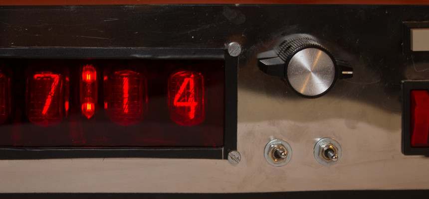
As I said, my friend gave me some thin metal sheet, which I used to make the front panel. I don’t have access to any CNC machines, so making holes is an arduous task, so I used a knife and a chisel to pierce the metal.
 I made some slight scratches to metal even tough I covered most of it by masking tape. I am not fully pleased with the result, but cutting metal with scissors, knife and improvised tools is a horrible experience. If I somehow manage to get the front panel cut by laser, it would look much better. Maybe some black plastic around the display hole would do the job… Well, it’s not that bad bud could be better…
And as for the front- panel markings, I don’t have any clue how I can make the text and the symbols. I have some designs, but it would require laser cutter/CNC machining, etching or other methods which aren’t easily available. Here is a one such a pan but the text around the rotary switch is too close to the edge of display and the vertical bars must be omitted. I must figure out something how to mark the buttons.

This eternity project: is far from complete. I must assemble the mainboard, make the metalwork on the case, to get the front panel and markings done, and write firmware for MEGA16. I have an initial code which reads time from RTC and transfers it to a LCD- display and to the I/O extenders, which output it to the nixie-drivers. No user interface(reading buttons, numeric menu system) nor alarm functions(alarm and sound) as of yet. I still have much to do, and I will be updating the blog as project goes forward.
Blog posts:
- Mainboard for nixie clock and burned fingers
- Crimping connectors and waiting blue smoke
- Why u no work >:C (first paragraph)
- I feel so stupid ಠ_ಠ
- Updated nixie clock schematic
- Itty Bitty Buck converter
- Nixie-clock update
- Nixie clock firmware
- What’s up? -Nothing special
- Small nixie clock firmware update