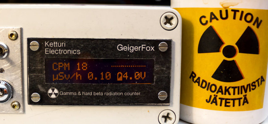
Modern physics, especially radioactivity has always fascinated me. How can something that can’t be seen, smelled or otherwise sensed by human have such a large part in our perceivable universe, and at the same time be deadly to us organic lifeforms? It can be bit frightening due its properties, but it still is everywhere and humans have harnessed it from medical and scientific triumphs to weapons of mass destruction. So how we can detect it then? Well, two smart men, Geiger and Müller invented and developed a gas-filled tube that can detect radiation and particles by ionization. This Geiger-Müller tube (shortly GM tube or informally Geiger tube) is the heart of the Geiger counter I built. I’ll skip the theoretical part which you can read from Wikipedia (or preferably its sources) and tell about the building process itself.
Couple months ago I found out that cheap new-old-stock of Soviet/Russian made GM tubes were available on ebay. I bought one from a Hungarian seller just before thing went sour in Ukraine. While waiting for the tube, I started to browse the Internet for schematics and completed projects to be used as an example. Many of them used weird high-voltage generation circuits with parts made of unobtainium. This site proved to be most resourceful and a big thanks goes to its original author. I based my project on that diy arduino based Geiger counter kit, and borrowed high voltage and detection circuitry and some open source firmware from it. It saved me a lot of work, mostly on software side which I’m not too fond of.
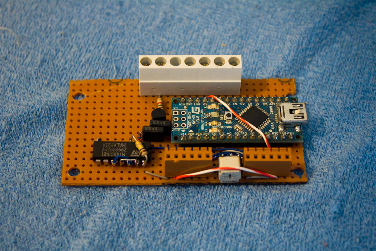
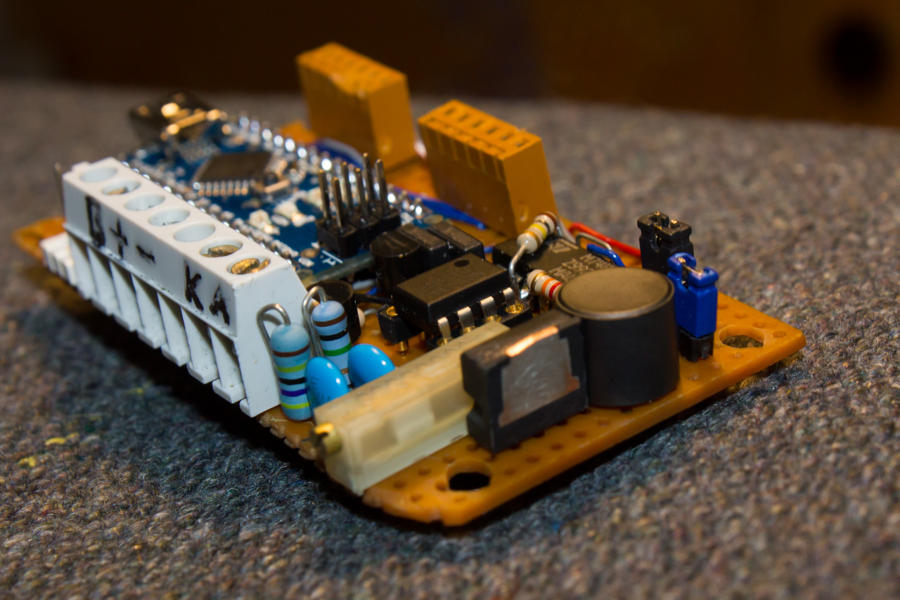
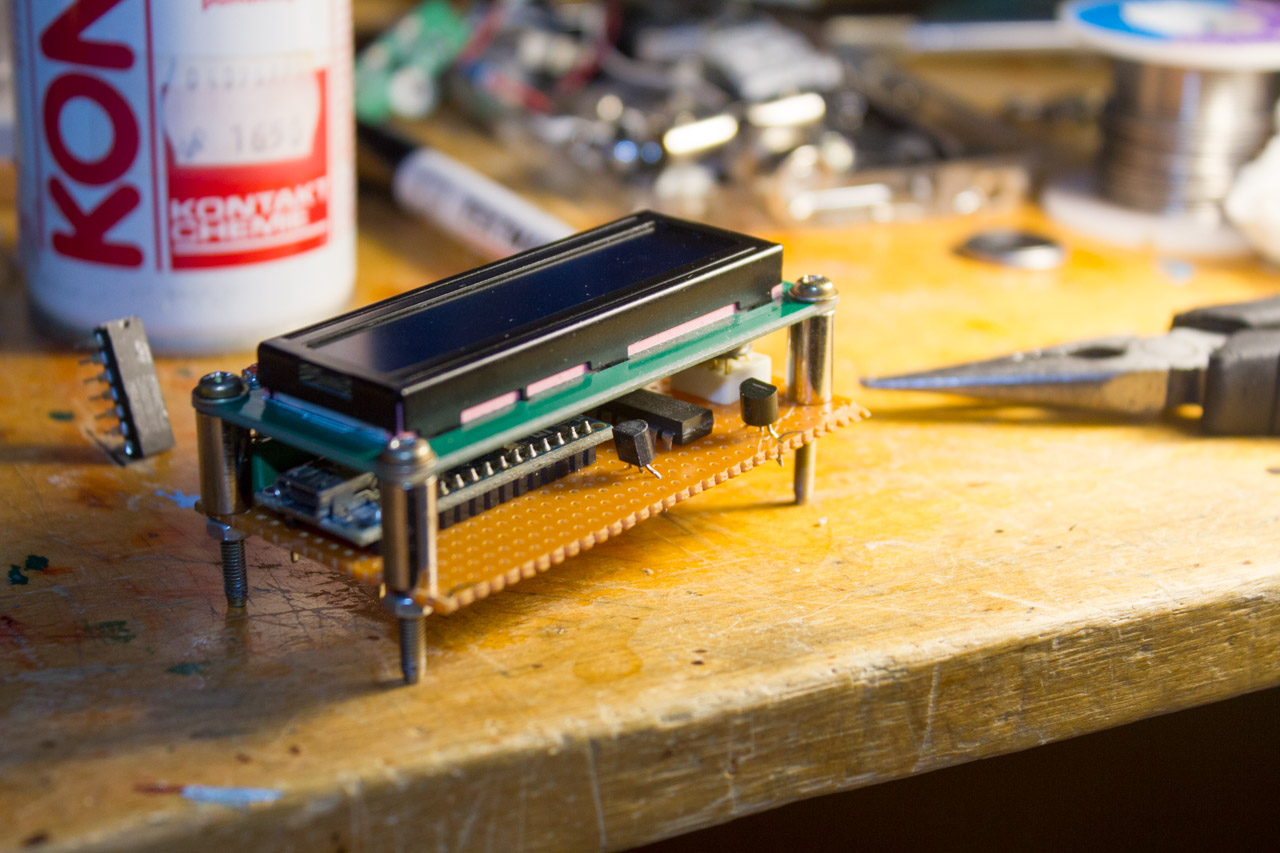 I had a vision to include everything needed to one circuit board the size of an LCD screen I would use, and attach them together with screws and spacers. Connection to LCD would be made with pin-headers. I used a Arduino Nano clone to save space and to get an easy USB-connection for data logging and firmware updating. Arduino has all needed circuitry to support AVR micro controller and FTDI usb-to-serial adapter. They are easy to learn and develop and ideal for hobbyist- and school projects.
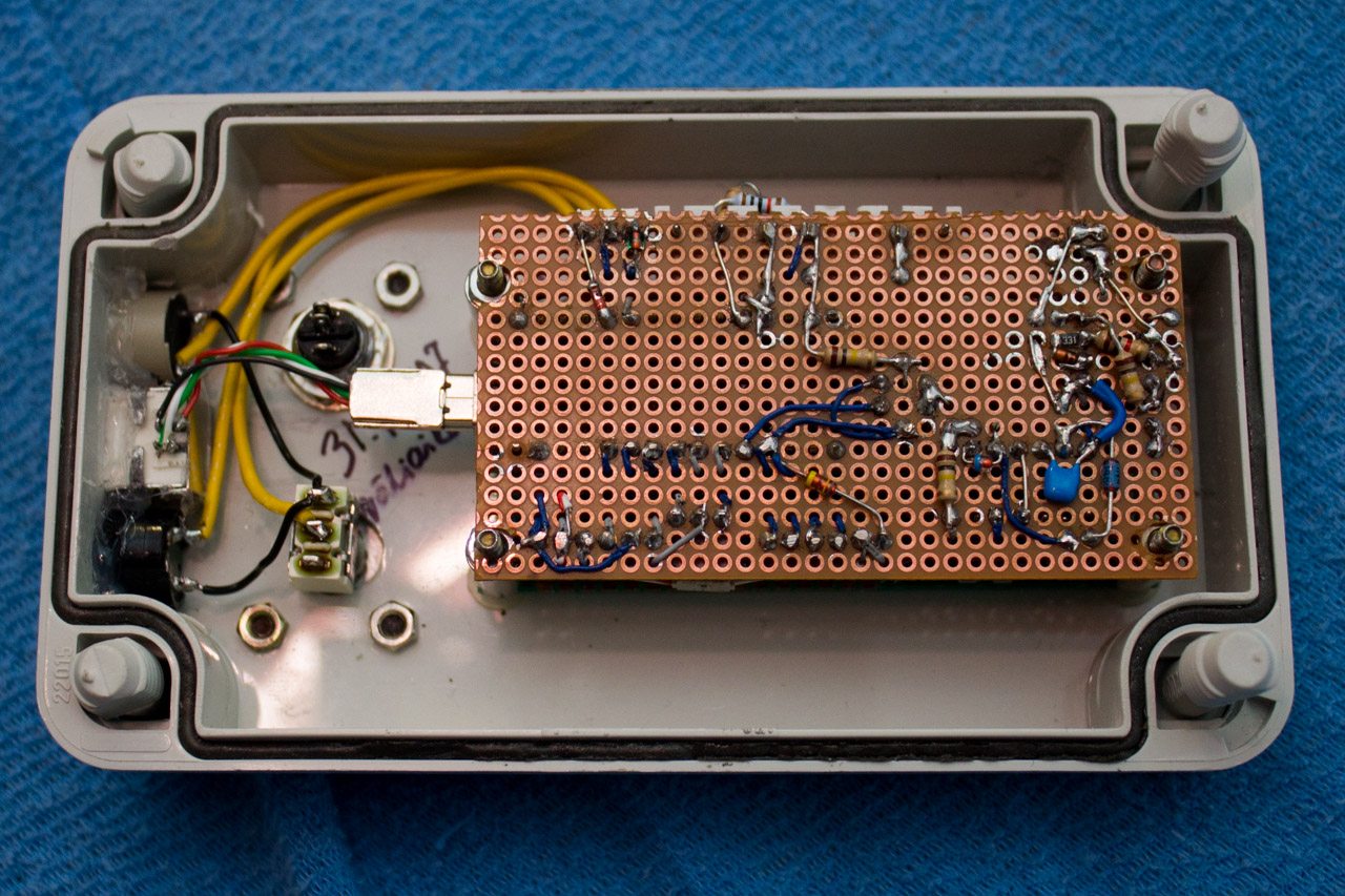
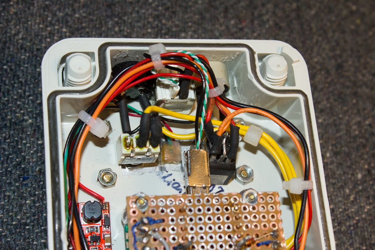
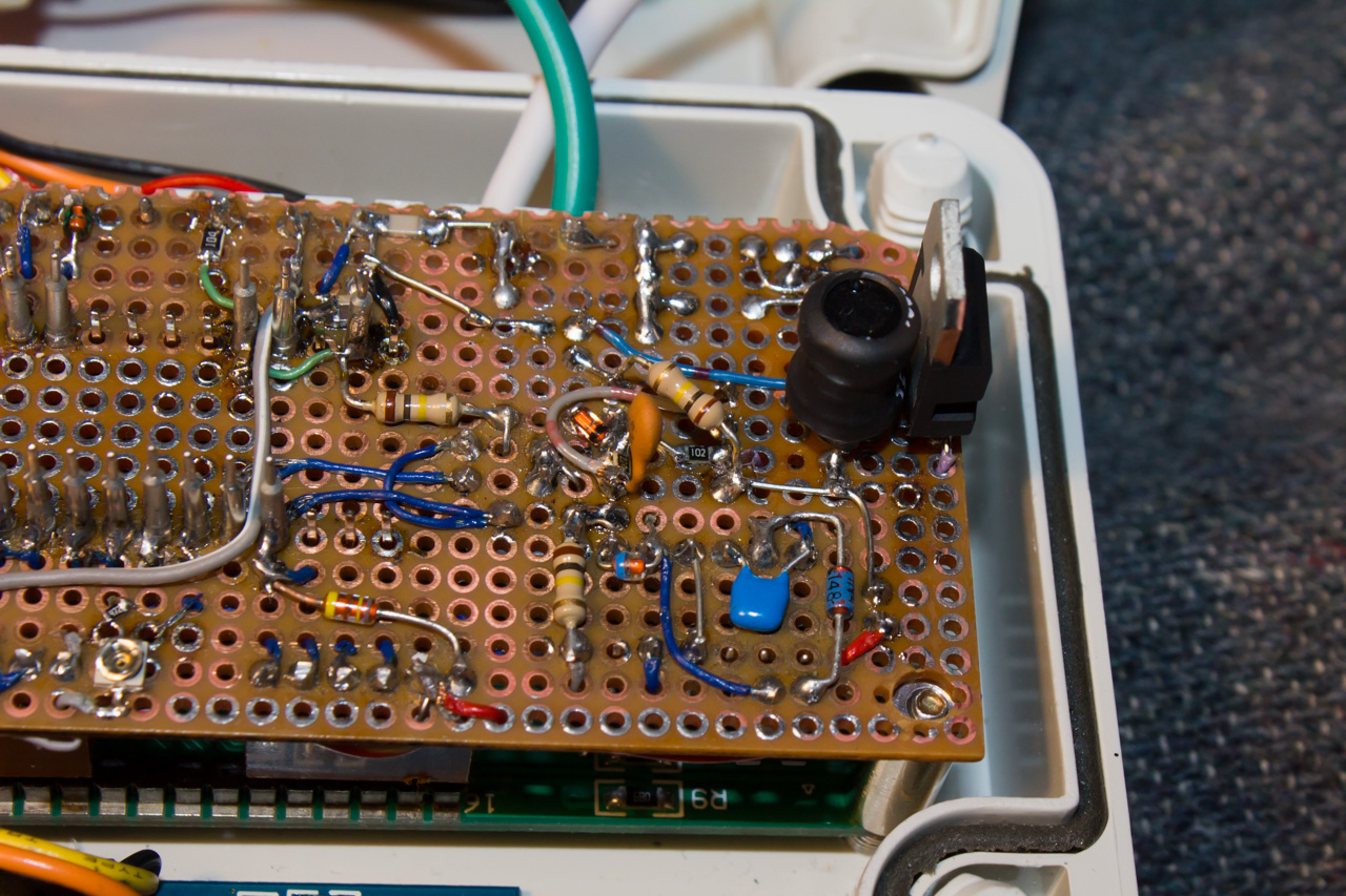
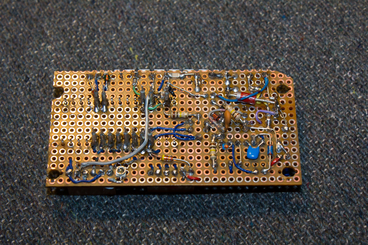
After making couple of crude mock-ups on component placement, I soldered them down and started a long and painful wiring operation. I made some bad mistakes during the project, and was forced to de-solder parts. Sadly this shows, as connections on final device are ugly and some solder pads detached from board and this caused other problems along the way.
First parts soldered together. Just so that the display and the pulse detection would work.
Famous words of Dr. Frankenstein. Don’t worry, readings shown are only simulated.

At least the circuit board is not far from Frankenstein’s monster.
 Sadly the first version of a HV-supply did not work out. I used an old 555 timer IC (that tincan on the right) that drew too much current even when just sitting there. Also, I did not have the proper parts for HV, so I added some transistors, resistors and capacitors to the shopping list and went back to drawing board.
Drilling and cutting without good equipment is hard.
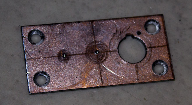
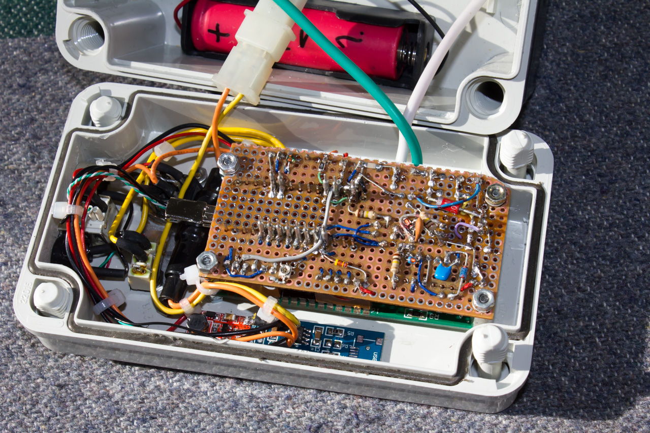
While having a pause from inhaling soldering smoke I made some parts for the case. Housing itself came from an old industrial wall switch (those white watertight plastic boxes). Making clean holes and cuts to ABS plastic did not work out as I planned and I wanted to highlight the user panels and the display. Hence the metallic switch plate and plastic display cover. Tools I had on hand were a hacksaw, a cordless drill and some files. Some creativity was needed and my methods probably would not be approved by any school or workplace (like hand-drilling holes to plastic by using screwdrivers and knifes). Considering that the aftermath was surprisingly good; all fingers still in place (just kidding) and even case for device in one piece and decent looking.

That red led did not end up in final device.
The hardest part was making a rectangular hole. Spinning drills do not make square holes, you know.
Rough edge will be covered under a plastic panel.
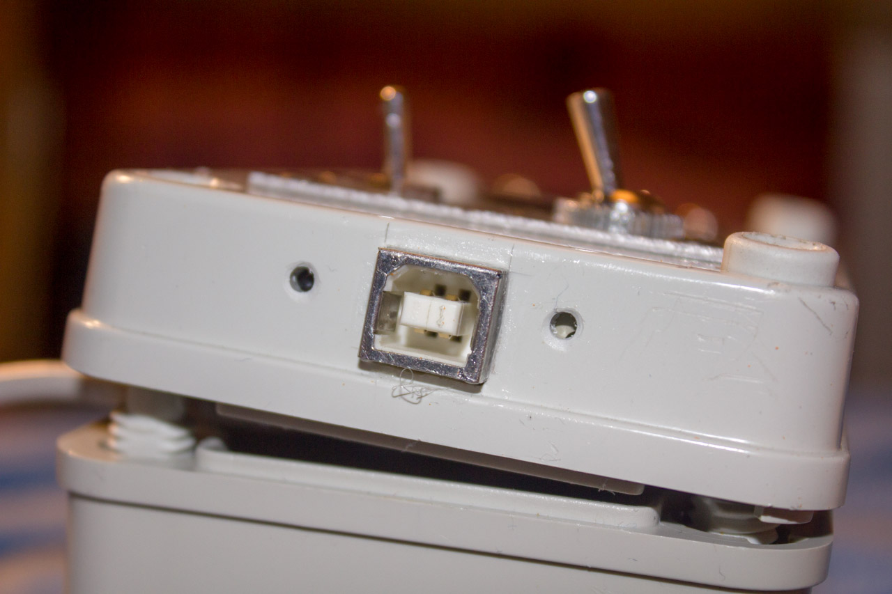
Another square hole for USB-connector. Smaller holes are for piezo speakers.
Some basic wiring for testing.
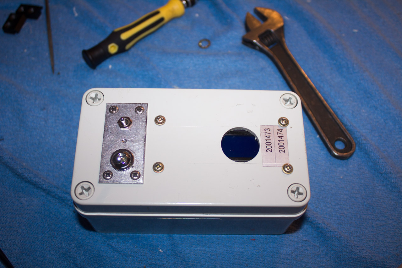
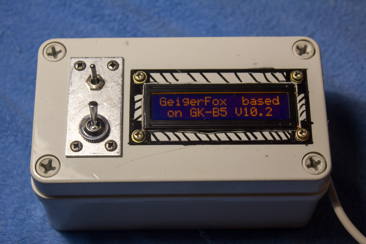
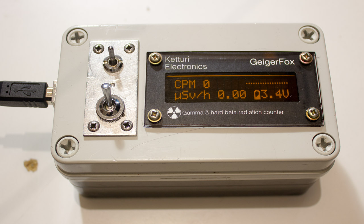
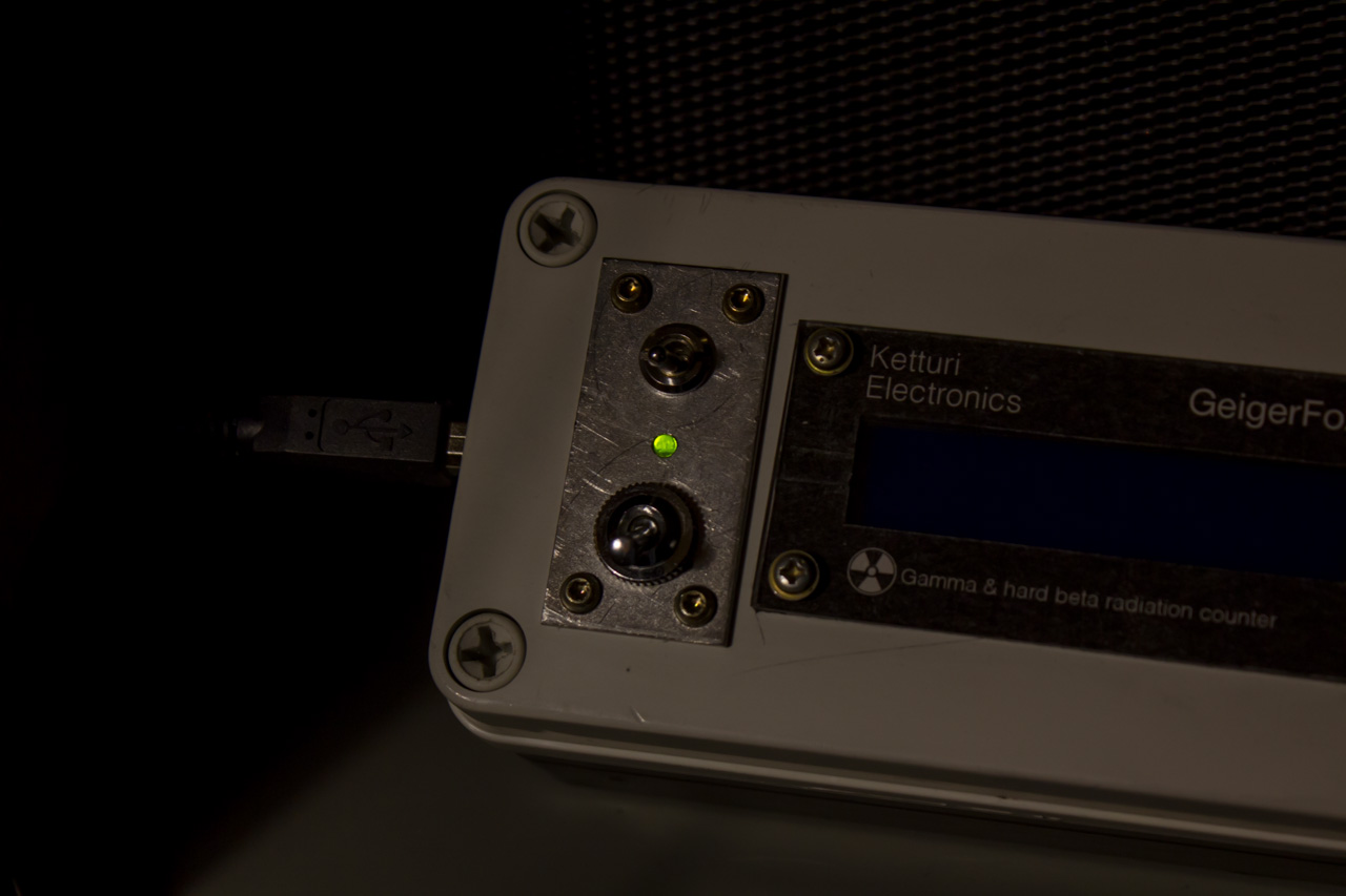
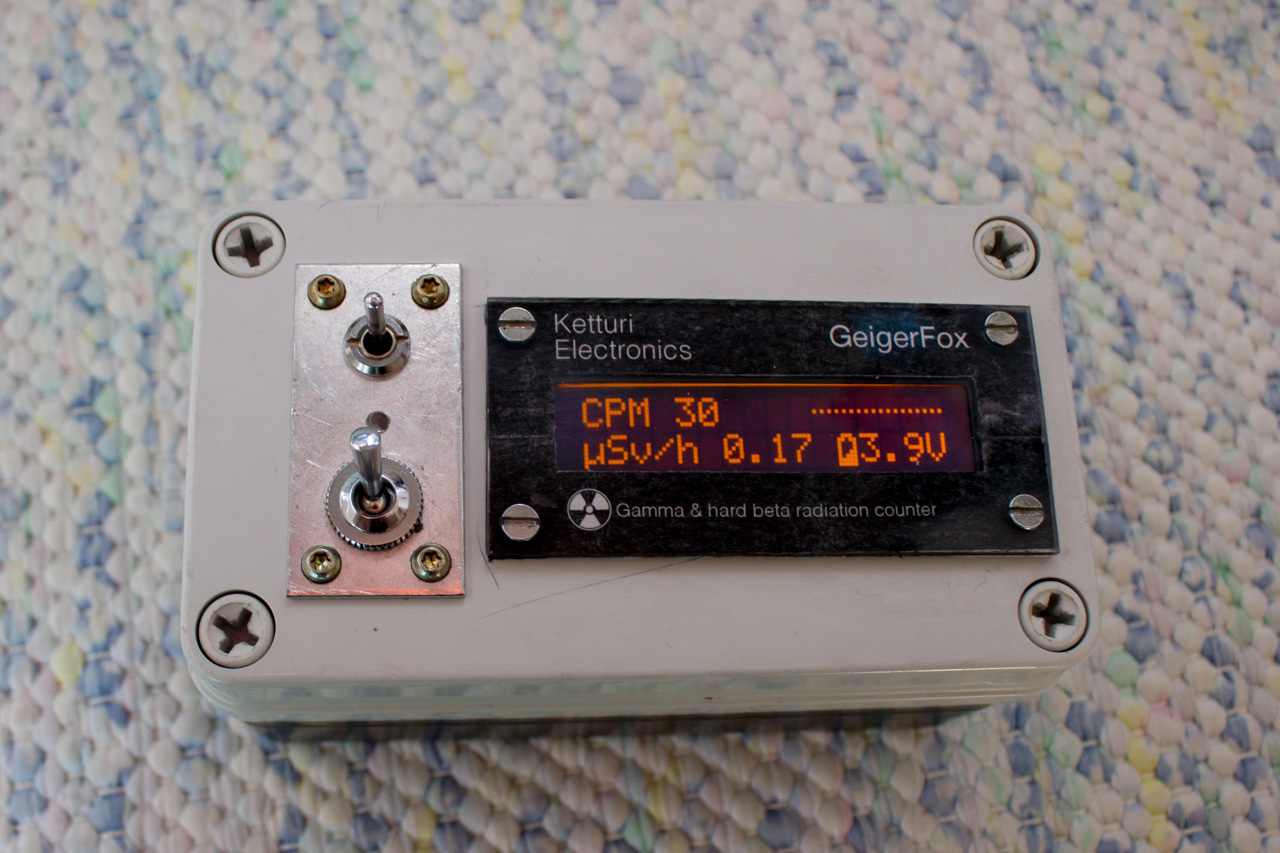
 The LCD is covered with plexiglass which protects it from hits and scrapes and also gives it a bit more professional look when label is applied under to underside. I designed a simple front label with GIMP and laser printed it to ordinary paper. Another purpose for metal and plastic panels are to maintain semi water- and dust-proof features for the box. After all you do not want any radioactive particles inside the meter, do you?

Cutting plexiglass is not easy. Best way is to make grooves with sharp knife and then snap piece of along the lines.
 The case had several versions too, and at this moment it still waits for the 3rd LCD plexpanel as one screw hole is in the wrong place and I tried to glue paper on it unsuccesfully. Lesson of this project is you should do your work properly, or you will need to redo it.

After the long waiting the post brought a very soviet-looking package.
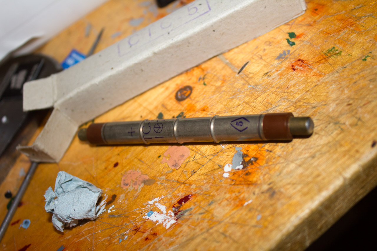
An actual GM tube! STS-5, similar to common SBM-20.
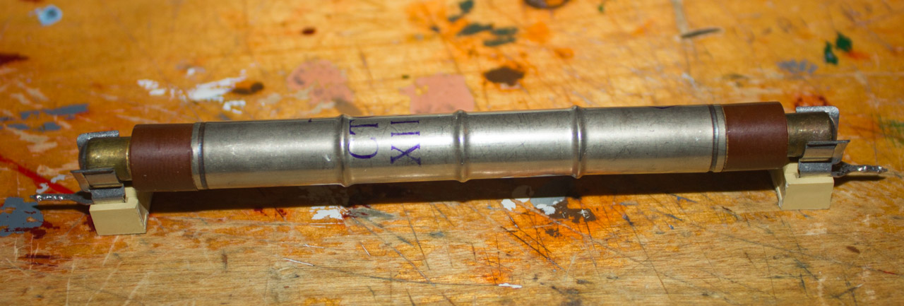
Glass-tube fuseholders used as tube holder. The tube can be changed without soldering,
This tube can detect mainly gamma radiation and some beta particles though a thick plastic case may stop all the particles except the very high energy ones. The tube didn’t rattle, and seemed to be in good condition despite one small dent. I do not know if calibration still holds in, as gas inside may have decayed or leaked. This tube may be military specked as it has that diamond marking with 5 inside. If I remember correctly it had something to do with the military. Some other military surplus parts from soviet area have had these markings too.
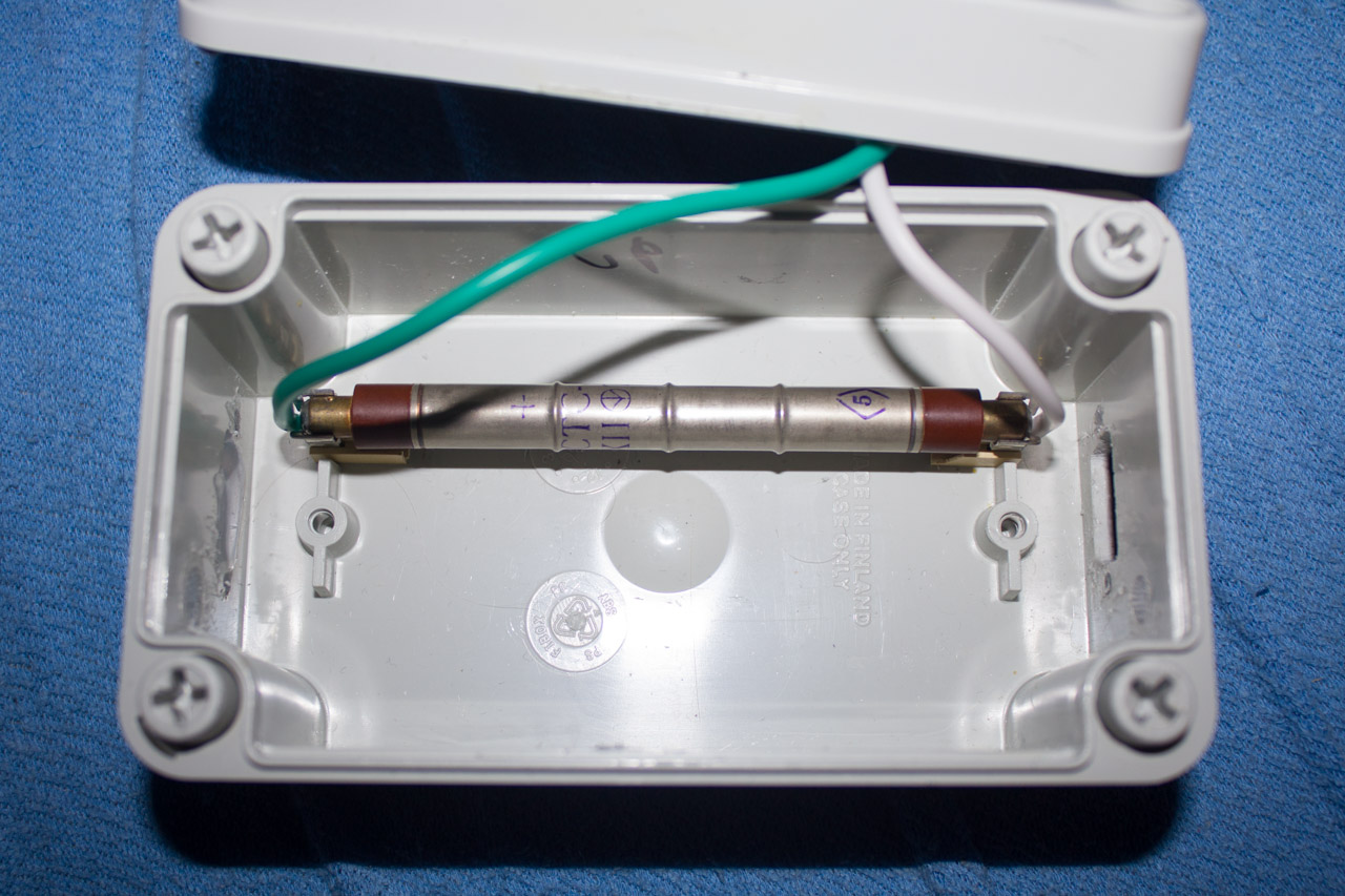
The tube mounted in case. Thick silicone leads are to minimize the leak current

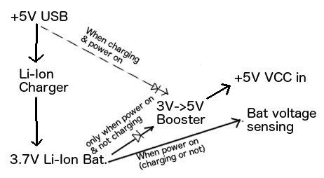 For the power source I chose a lithium-ion battery cell. The 18650 cell type is readily available as it is used in many laptops, flashlights and so on. I recycled some batteries from an old laptop. For charging I bought a 5V USB-charger board from DX.com. It charges the battery while the device is connected to USB. When using a lithium-ion battery there is no need to discharge it completely before a recharge. It may even damage the device if the battery voltage goes under 3.2V or so. I have an alarm that goes off if the battery level reaches 3.2v, but it does not have a cutoff circuit yet. I have a plan to buy a protected lithium-ion cell that has built-in protection for under- and overvoltage. As the lithium-ion battery only gives voltage between 4.2V to 3.2V, I need something that iccreases it to a steady 5V supply. If the voltage changes, it messes up the contrast oft the display. The voltage of the tube may vary as well, causing some accuracy issues. I bought a small switching mode power supply from DX.com that increases 1-5V to a steady 5.2V. While the USB is connected, the device works with 5V from there, and the current from battery is not drawn. Otherwise the Li-Ion charger would not know when to stop charging. First it starts to charge in a full 500mA current, but when voltage rises it starts to limit the current with a constant 4.2 voltage. When the battery is full the current flow stops, and the charger stops, which turns the red light green. Battery voltage can be constantly seen on display because I connected the battery to the Arduino’s analog-to-digital converter. This is the main difference to original diy-geigercounter kit.

The battery mounted next to the GM tube
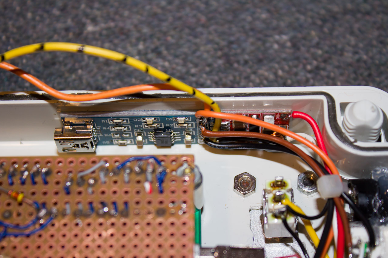
The battery charger and the power supply connected. Later I moved them to different position.
I drilled hole for the charging indicator.
Internal wiring.
Full battery.
After I got the charging and the power supply working a new problem came up. I could not get the Arduino detected when I connected the USB to the computer. I changed all my wiring and connectors, even bought new Arduino boards. It was infuriating. Nothing helped and whenever the Arduino was powered by an external source and USB was connected, the computer would just show the “Unrecognized device”-popup. If I removed the Arduino from the board, and connected it separately, it worked. Only after de-soldering the board twice, and trying three different Arduinos I found out that fault was in Arduino itself! All boards, clones and genuine, have same thing. FTDI FT232 USB to Serial bridges datasheet notes that the “TEST” pin must be connected to ground, or the USB will not work. Well, someone designing the original Arduino had not noticed that, and the “TEST” pin was floating freely, not connected to anything. If there was a charge that would pull the signal up, the USB would not work. After connecting that signal pin to ground everything started to work. So much work wasted when fault was already there in bought factory-made parts. Still… I’m happy that it was so simple to fix and I could get the whole device to work properly.
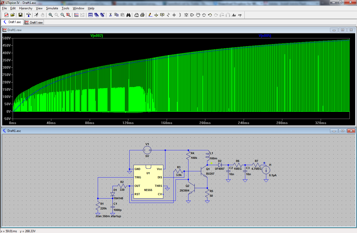
I did run simulations to determine how the high voltage supply would work.
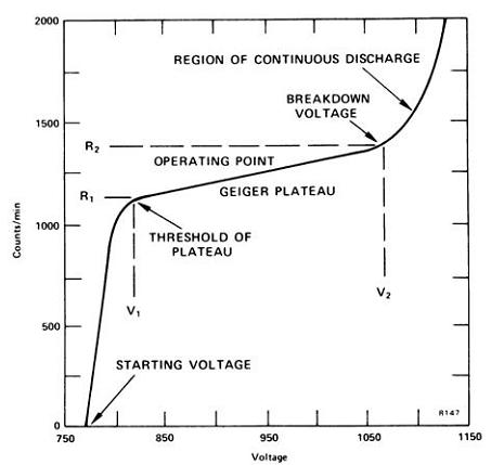
The GM tube plateau
After there was no problems with other circuitry, I continued to the high voltage supply. Geiger-Müller tubes need high voltage to work, because ionization and avalanche would not happen with lower voltages. The tube I used needs approximately 400V to work. Good thing is that GM tubes are not that picky, because they work as long as the voltage is inside the plateau region. It can have an impact on the results received, but just marginally. Getting the voltage right is difficult as it cannot be measured with ordinary multimeter. The 10Mohm impedance of the meter is too low, and it lowers the voltage down. I get only about 80V while the tube is working when a meter is not connected. I just started without a voltage meter, and turned the voltage up until I started to get results. Then I tweaked it just little bit up and left it there. Later it proved to actually be on the high side, as I got 0.2µSv/h when the nominal background radiation level was 0.109µSv/h measured by STUK (they have background radiation measurement network on every major city and village here in Finland).
High voltage still not working.
Building switch mode power supplies is always a bit tricky. They work on higher frequencies where stray capacitances and magnetic fields start to affect. I bought some parts from a Finnish electronics webshop, and soldered them in, and got high voltage on the first try! It just wasn’t steady. The voltage was fluctuating up and down, and every time I tried to close the case the meter would go crazy. Even without the tube connected it would show huge amount of counts and piezo speaker would ring constantly. Yet again I desoldered everything.
Third time’s the go I guess
For the third revision of the high voltage supply I changed some parts. The potentiometer I used previously had an overly high value, 50Kohm when the range for high voltage is not even 100ohm. The adjustment range with that one was so narrow that even breathing towards to it could change its value. I replaced it with 2Kohm 20 turn one that could be adjusted much more precisely. Good thing that I had those lying around. Also, the inductor that induces high voltage spikes was replaced to one that had a better ferrite core. Lastly, I changed the diode, not because it was not working, but because I somehow misplaced it during my build process. I still haven’t found it, and I believe it may had have something to do with The Borrowers.
This version worked and I got my second counts (I had previously tested the GM tube using 500V from my insulation tester). It was the first time that the meter could work on its own, at least.
Hack there and bodge here
Nearly complete wiring and board.
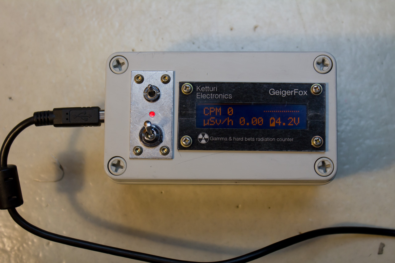
In one piece
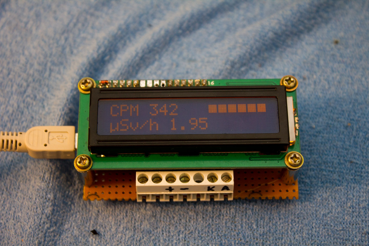
 At this point I had a fully working Geiger counter which could measure radiation rate and data log values to a computer. I did a short logging test run to see if background radiation would match to STUKs measurements. Of course, it depends very much on the place, as ground has all kind of isotopes of elements, and man-made fallout.
 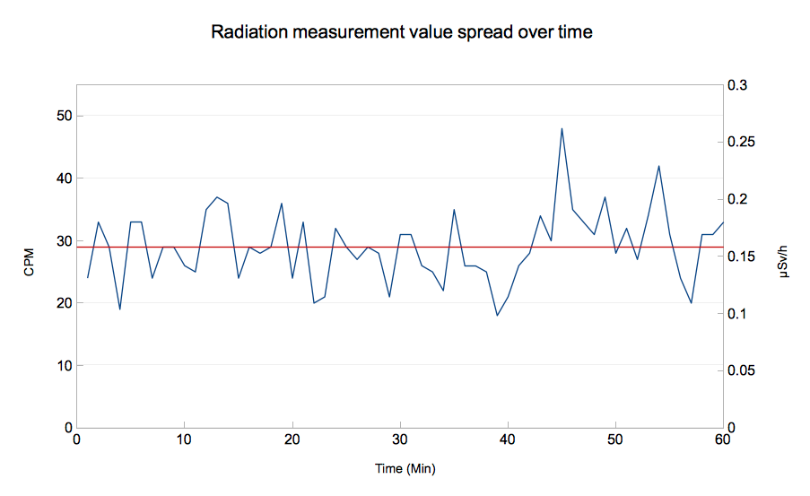 As you can see, the average value is a bit high, it should be nearer 0.1µSv/h. I made a slightly longer data logging period to get some more accurate data.
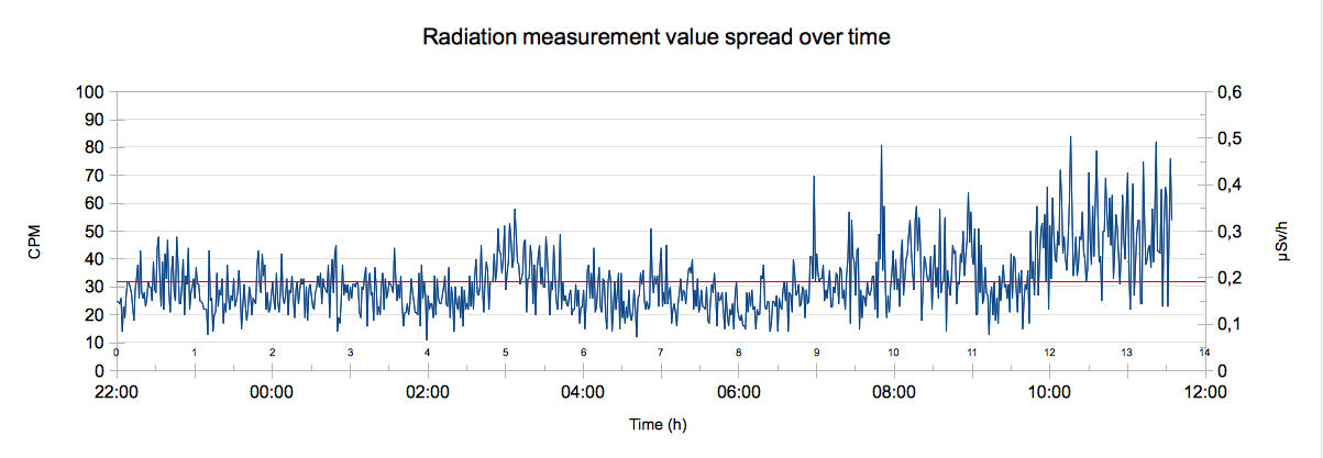
This should not be happening.
For 12h measurement period I got some weird results. What’s with the sudden peak at the end? The average is two times too high as well. I turned high voltage adjustment a little bit down and values came right down to what was expected. I did not thought that it would affect the reading so much. That rising at the end, could it be due to the sunrise? It starts to rise after clock 7. Maybe it was too sensitive when excessive voltage was applied.
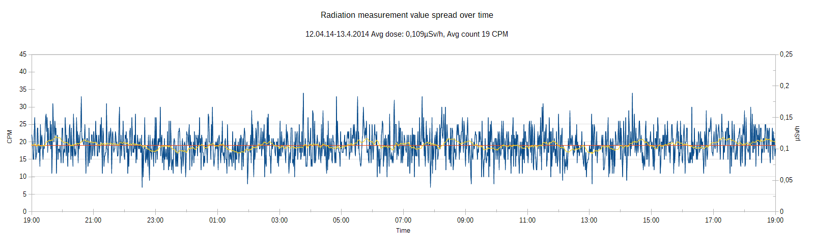 After recording of 24h of data with a lower voltage, I got this. Just what I was expecting. Normal spread that averages to similar values that official levels were at that time. I emailed to my lukio’s (Finnish school) physics teacher and asked if I could compare my readings to the Geiger dose meter of the school.
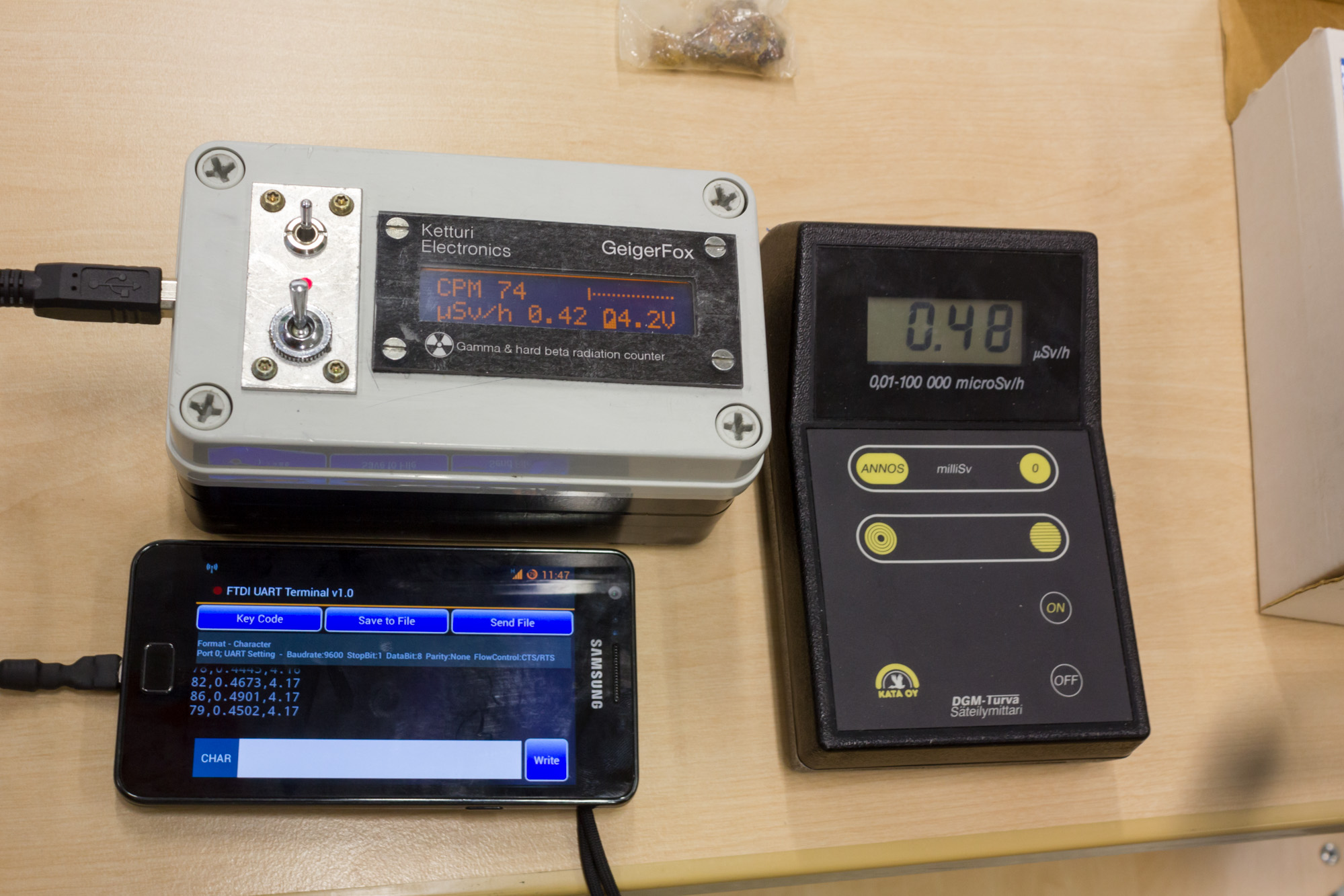
Comparison between meters.
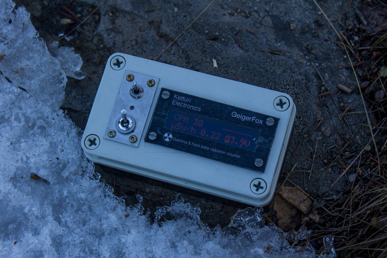
I got a very similar readings from a uranium-rich ore sample. Notice, how my meter is connected to my Android phone with a USB-OTG cable. Radiation can’t be measured absolutely, so I’m pretty happy with the readings I got.
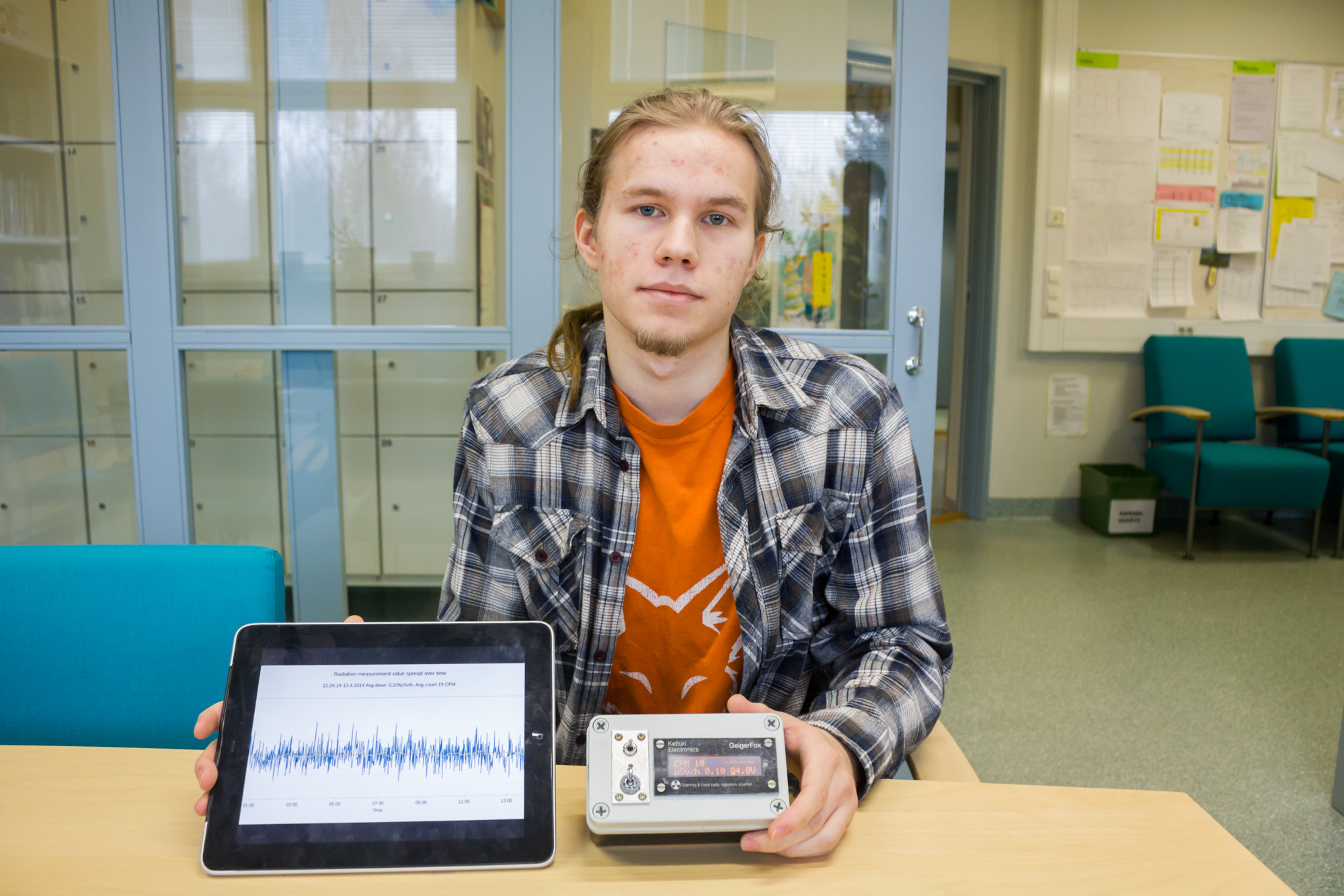
Proud maker showing his accomplishment!
Closing words. This has been an interesting project that has shown me some important things. I could have done it even better, from build view to project managing. I could have planned it better before starting to make the parts. Doing so, I would have avoided some of the mistakes and the redoing of some parts. Maybe I should have used a real PCB. Also , some would say that making my own firmware and circuit design would have been more meritorious, and some other would have wanted to see more work done together by the hacker and maker community. As an open source project I can contribute more.
But nevertheless, this was not a worthless project at all. Now I have a working radiation meter which I could use in various scientific experiments and projects (e.g how weather and season factors to background radiation levels). And as always with my projects, this is not the end. I can always add things and change or repair some. Fro example, I’m waiting for an additional switch to change between display modes, and a new display plate that has some better aligned screw holes.
One has to just continue experimenting and creating things so we can keep this world from ruining and to advance it. Even accidents like Chernobyl, Fukushima and countless others have contributed our science and society.
And it can fit in your pocket, Good for checking out the radiation on foods like Seafood, Bananas.. Great For Open Food Market’s For like Fish Buyer’s. You should Put it up on Gofund me web sites.. and sell it to the Food market’s..
I’ll help, And I was thinking of something.. but Just forgot it from Laggin internet..Something to do with..hmm..
You have a 3D-Printer..and some aluminium foil.. How Much can HIGH Dose We can Shield it before it Fails, I can Same a few Spots in the World where they throw it on a Robot with Duct Tape, Drop them in and Get a reading off of it before the System runs out of power, or Fails..Hmmm..