 Canon X-07 is great little handheld retro computer. But being Canon, nothin is standard. Canon has always insisted using weird proprietary connector for devices, and usually it is impossible to find connectors that would fit them. This is also a case with X-07. It uses weird connectors for serial- and parallel ports. They look bit like a normal D-sub connector, and D-sub connector almost fits into them, but it is not a good fit. I wanted to make new connector that matches X-07’s serial port perfectly, so I took my callipers and 3D cad and started to work.
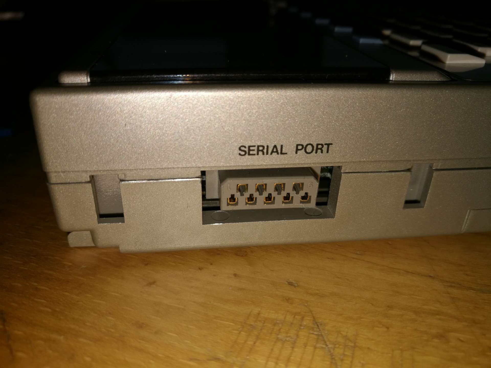
First I had to take measurements from the original female connector that sits in X-07. To ease job, I carefully disassembled whole computer, and even more carefully desoldered original connector. I then started to take measurements from every possible point. And oh boy this is one weird connector. Pin pitch is 3mm x 2.5mm for the contacts, and in original connector they are staggered blade types. Luckily, connector also accepts pretty much any round contacts that fit into the holes. Some measures are imperial, e.g. length of connector is really really close to 15.875mm, which is 5/8 inches. Some measures are definitely in metric, and some do not match either systems. Anyway, I got all measures done and sketched them with Autodesk Fusion 360 cad. Then it was just extruding connector body to 3D space, and editing details in. I did not model contacts, but otherwise I got closely matching 3D model of original X-07 serial connector. Here is live 3D view of part I modeled:
After I had cad model of the original part, I could start to model matching piece. I started with shroud that fits over original connector body. Then I placed larger flange at top of it, that would keep it in place inside connector casing. I took D-sub male connector apart, so I could see how contact pins were hold inside, and decided to copy that design so I could use same pins as they do fit inside original connector. In D-sub connectors pins are hold between two plastic insulators and insulators have holes, that are larger at inside than outside. Contact pins have flange, that sits between insulator plates and keeps them in place. These plates are then hold together by metal clips that also form outer shell of connector.
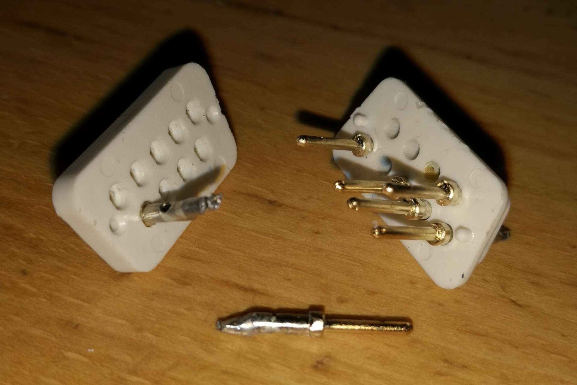
It was quite easy to design connector with these pins. Front shell of connector has circular 1mm holes front, and 2mm holes at back that have narrower sides so pins will not rotate when in place. Backside just has 1.5 mm holes. I copied pin arrangement from original connector, and placed appropriate holes for pins.
Then I just had do design outer casing, that would hold both pieces of connector tightly together, and provide strain relief for cable. This part of design was pretty much freehand modeling. I placed square block and started to edit its features with various tools until I had body that somewhat looked like a store bought connector casing would.
When I was happy enough with the 3D model, I packed my computer and went to Tampere Hacklab so that I could 3D print first test versions of connector. I was quite sure I got it right at first time, but you can never be sure before you print physical version of model. Usually 3D printed parts are not that accurate, and often need some hand work to make them fit.
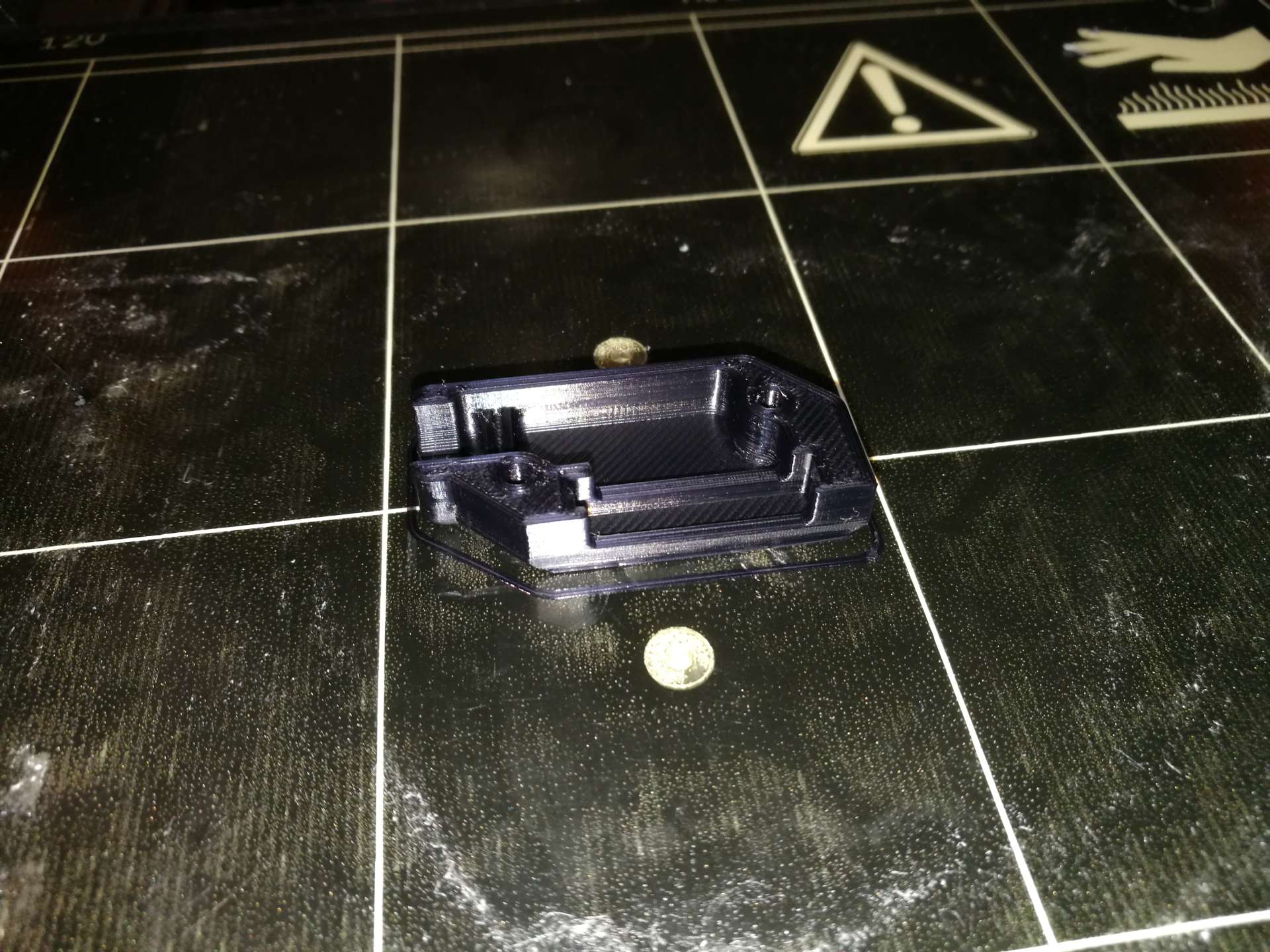 I printed parts with Prusa i3 MK2. Print bed was quite worn out as somebody had used sharp tools to remove parts and used wrong settings so hot nozzle had left some marks on the print bed. I should have placed part at the edge of the printable area where surface is not so worn.
I had to clean out holes with small drill. After removing spurs and leftover strings from filament, pins went straight in.
 Back plate that holds pins in the connector could not be printed. As contact pins have to be in place while soldering them, soft PLA plastic from the printer would just melt away while soldering wires to contacts. I laser cutted pin holder from thin acrylic sheet, but delrin or other heat resistant rigid plastic would be even better.
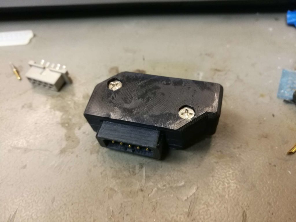
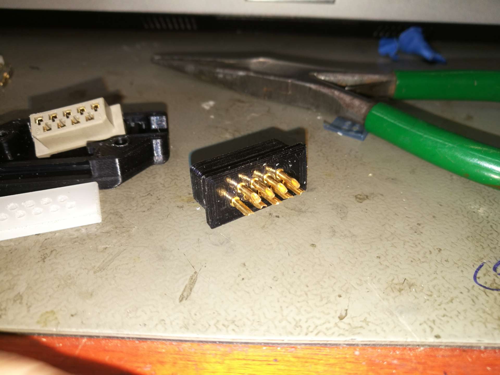
 Assembled connector for test fit. I had to file down the white pin holder part, so It would fit inside grooves that hold connector inside casing. I am not that happy with surface of top and bottom, marks in printer bed were left to plastic and I was too lazy to use sandpaper and filler to smooth parts.
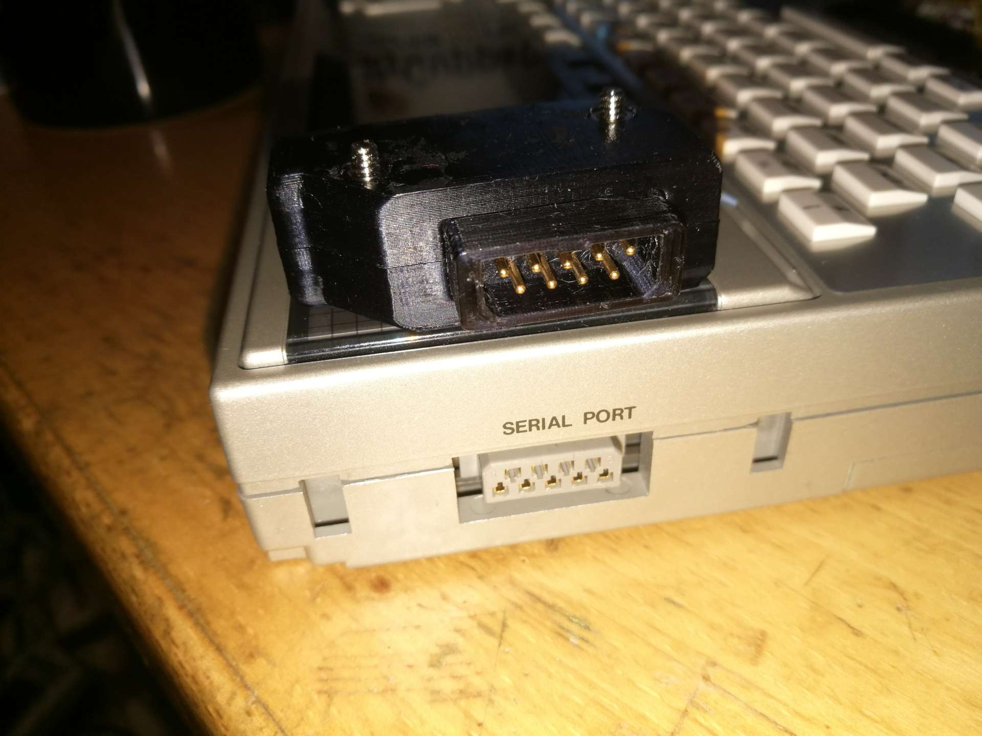
Connector fits quite perfectly into the Canon X-07 port. It is not too tight but holds well, and all contacts are making good connection.
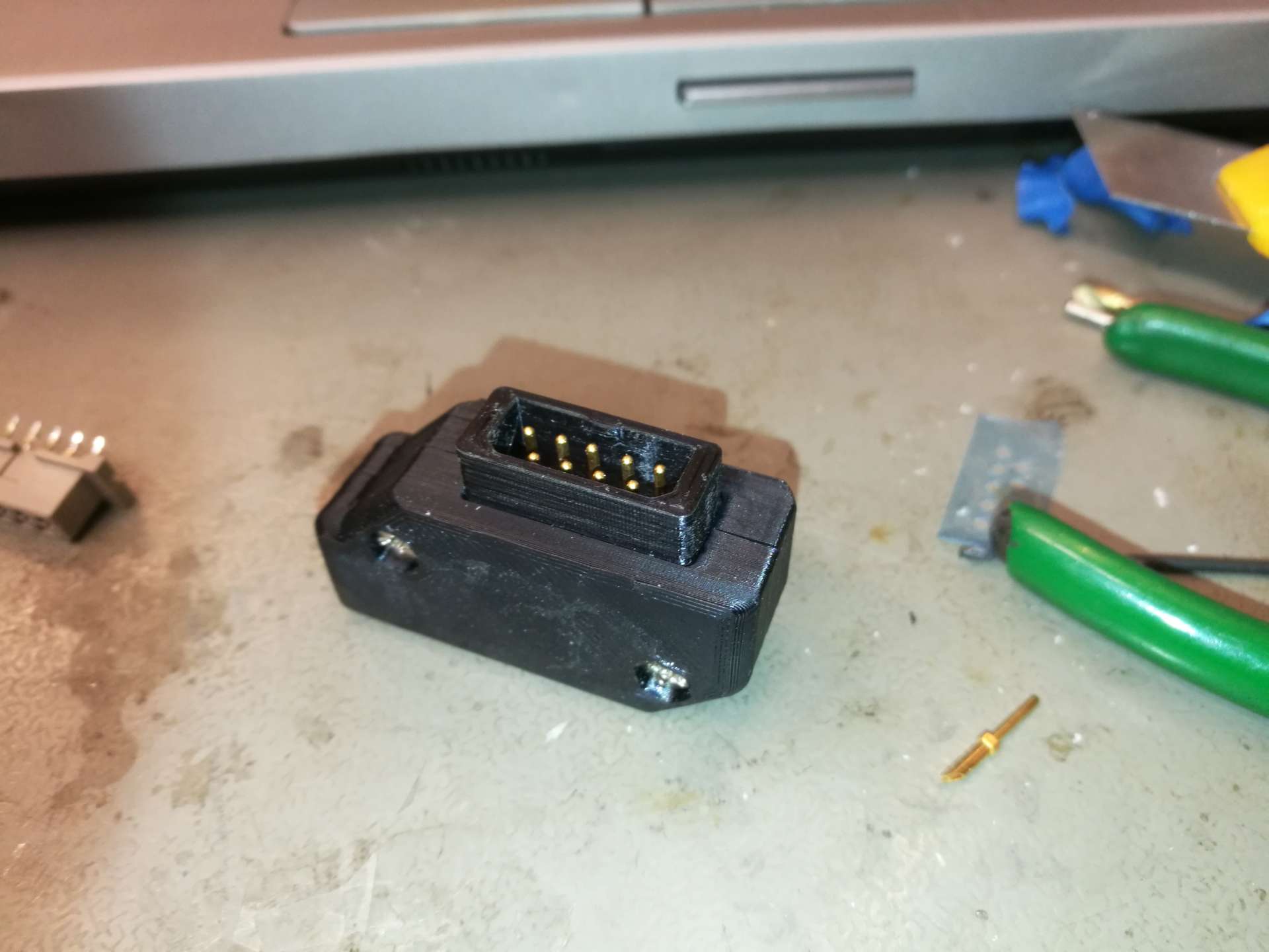
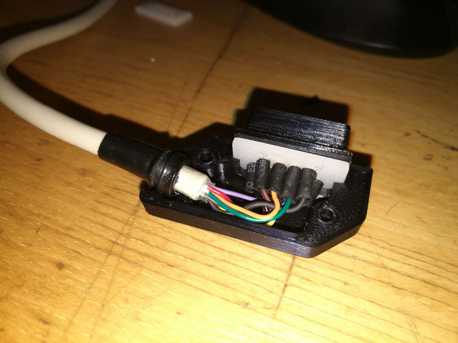 I soldered cable on contacts. Printed partes were not installed during soldering, and white acrylic pin holder did not melt like printed parts would have been. I also installed small strain relief rubber jacket over cable. Other end is just terminated with normal pin-header style connector, so that I can plug it into USB -> TTL serial port adapter. X-07 uses ~5V logic in the serial port, and it cannot be connected to normal RS232 port without level converter circuitry. There is also 4.6V output from batteries in one pin, that could power level converter, IR transmitter or maybe even bluetooth serial adapter. Connector also has software switchable 38,4kHz signal for infrared transmission modulation.
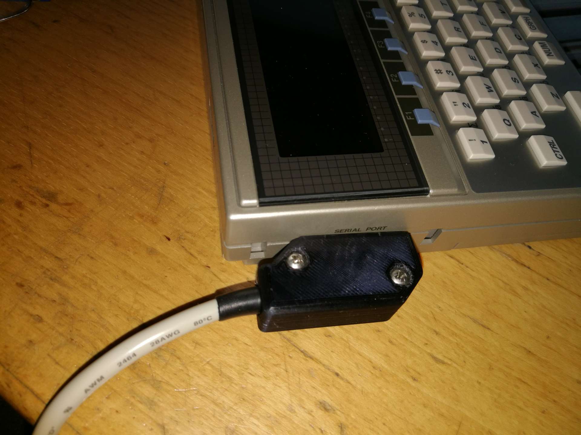
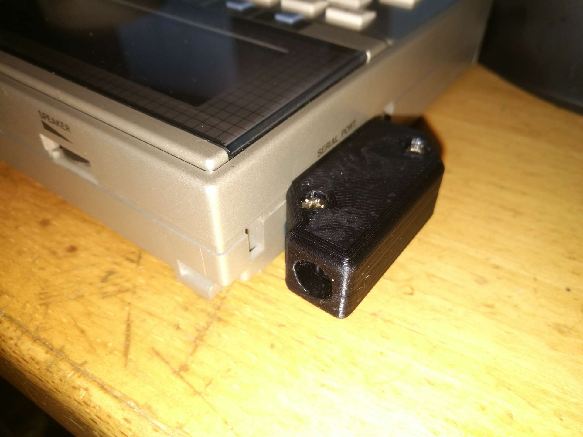
New connector on old system. It turned out really well, but there are some cosmetic issues that I will fix in the next version. I am planning to build serial cable with integrated FTDI chip so that I could connect X-07 straight to USB. I also want to make similar connector for 15 pin parallel port that could be used to connect printer to X-07, or control other 8-bit parallel devices.
hello! Would you share the stl files? cool work!
Hi, You can find them from here:
https://ketturi.kapsi.fi/canon-x07/
Hello, just found your post. Great job! Did you succeed to build the USB cable ? With your cable, can you upload programs into the X-07?
I would be very insterested in building such a cable.
Kind regards
Dominique