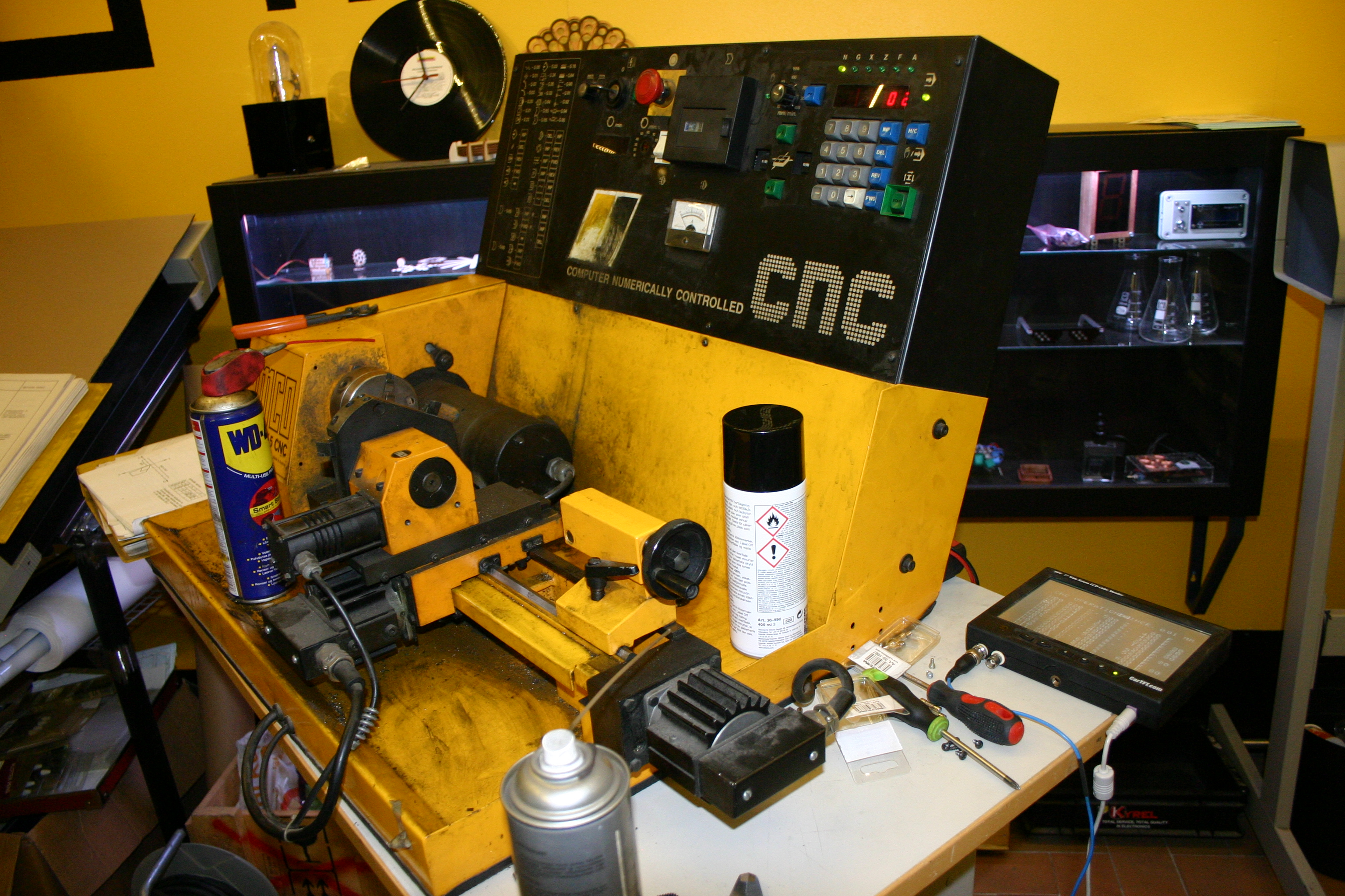
 During renovation of Emco Compact 5 cnc-lathe, I got my hands on scrapped electronics of original control cabinet. I saved some of the more interesting boards, like one that acts as rudimentary GPU. Whole video board was separate add-on, that contained video processor, video RAM, character-ROM and RS232 transceiver, and connected to main CPU board with large 32pin bus connector.
I took my multimeter, scope and logic analyzer, and stared to reverse engineer the mystics of this video controller.
Board in question has infamous Motorola 6845 CRTC, which was very common video IC of that era. MC6845 could be also found from many other computer systems, from Apple II to IBM PC CGA video adapter. Not only in computers, MC6845 was used also in many video terminals and other systems, that needed ability to show text and graphics on CRT monitor. Later functionality of MC6845 was transferred to more modern video adapters like EGA and VGA.
Maybe popularity of MC6845 came from its simple but versatile design. On the bottom, it was just programmable timing generator, that provided horizontal and vertical sync pulses, and scanning for video memory address bus. It could not draw pixels on screen by itself, and needed bunch of other logic and memory circuitry to make usable video output.
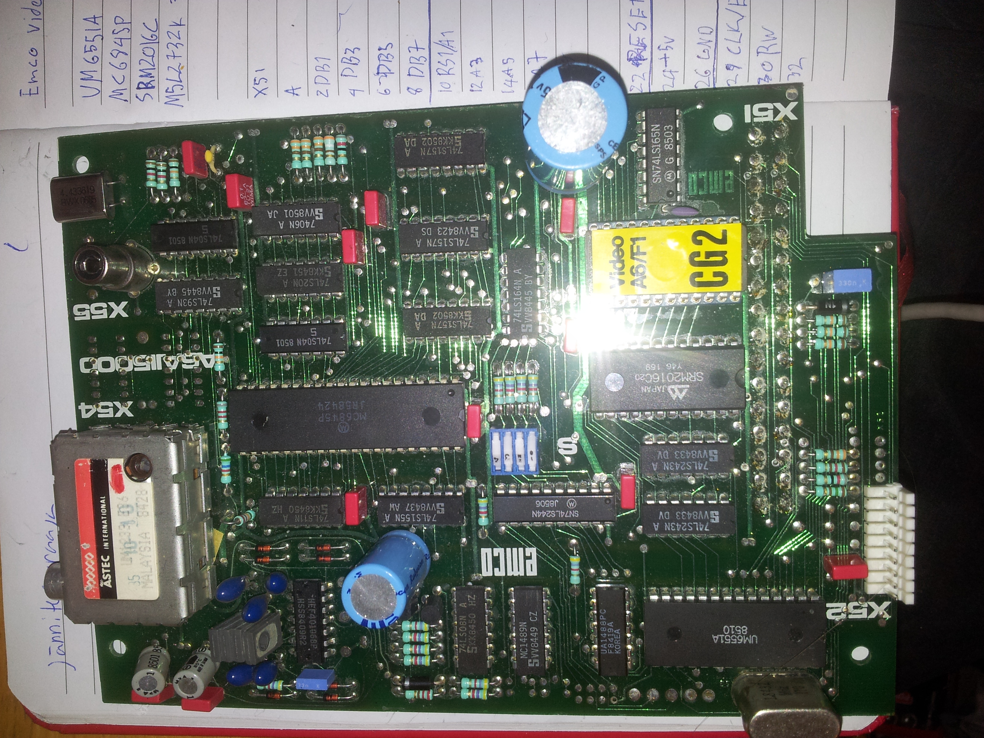
Emco video controller has 2k SRAM, 32k ROM and discrete logic for creating needed signals and graphics. Due simplicity of circuitry, it is limited only to alphanumeric mode, where ram stores character code at specific display position, and characters are shown from ROM. Board was used only to show simple table of CNC G-code instructions during programming of Emco lathe, and simple video interface was enough to do that.
Hardware

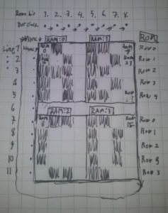
Nothing beats old fashioned notebook and pen
I began to reverse engineer board with flying probe technique, where one lead of continuity tester is held on desired point, and other one is dragged trough all of the IC pins, until connection is found. I had pinouts of every IC on board, and quickly managed to map out connections of CPU bus connector. This was not enough to understand workings of video controller, but gave some clues how system was transferring binary data to human readable display format. Board has motorola style bus, that has 8-bit data line, and 11-bit address lines with some additional control signals.
I continued painstakingly map out every connection between IC’s and passives on board, and trough measuring and noting down I had pretty good idea, how everything connected together. I managed to draw full schematic, that shows how system is put together. I also divided components in logical blocks, that describe functions of component groups. Roughly, it contains CRT controller, RAM address bus switching, RAM&logic, Character generation and video output, output buffering, and finally clock generation.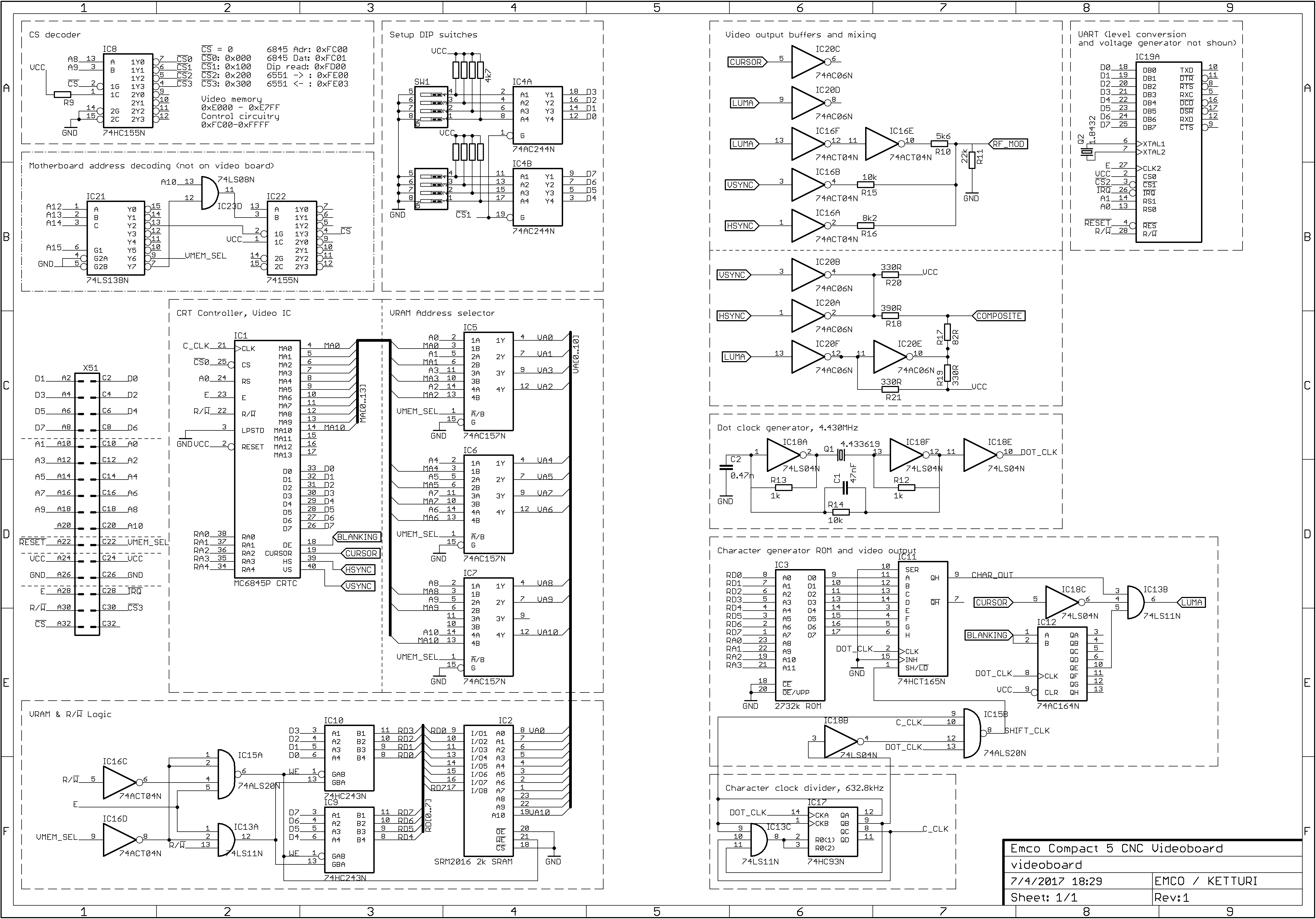
As you can see from schematics, video RAM is connected trough 3 digital address switches and 2 data buffers. When CPU wants to write data on video memory, RAM is disconnected from CRT controller, and connected straight to CPU. Then CPU can read and write memory as it wants. During this time video output is still active, but shows artifacts due missing ram scanning. When CPU is done, it returns control of RAM to CRTC, that keeps scanning trough RAM address bus, timing scans to horizontal and vertical sync cycle.
Output of video RAM data lines are connected straight to lower ROM address inputs. Also, row address line from CRTC is connected to upper address input of ROM. CRTC selects pixel row of character burned in ROM, and data from RAM selects character to be displayed. Data output of ROM is connected to shift register, that converts parallel output of ROM to serial stream of bits. Clock circuitry and CRTC keeps serial stream in sync with character and H&V -sync. Then outputted serial stream is added to sync signals and buffered to video output.
 If you know how CRT television works, it is possible to follow working of Emco videoboard.
First, vertical sync tells that we are in upper left corner of display. CRTC selects line 1 from character ROM and first character from RAM. First row of 8 pixel wide character is loaded onto shift register, and pixel clock fires out black and white dots into the video signal(1). When this is done, CRTC selects next character from RAM, and this is repeated until first line is full.Then CRTC selects line 2 from ROM and again first character from RAM(2).
Second line of characters is outputted into video signal. This continues until whole 16 rows high character row is drawn on screen, and CRTC moves one row of characters downwards in RAM. Now whole thing continues as previously, until whole screen is filled, and returns at the top of display(3).
It may seem complicated at first, but knowing how television and raster scanning works, it is similat to that. There is just multiple repeating scannings done, one inside the ram and character rom, and another on display output image.
Software
After I had schematics, I could focus on software side of controlling the Emco video board. CRTC IC itself has dataline for writing bytes into control registers. These registers tells the CRTC how to time different sync signals, how to scan RAM and ROM and other important configurations that drive video signal. In this case, I had to get original register values from Emco CPU, so I could determine timing and memory layout correctly. First i read content of CPU ROMs, but I could not disassemble them correctly to get those register variables. Then I just connected logic analyzer to CRTC chip, and recorded initialization sequence. 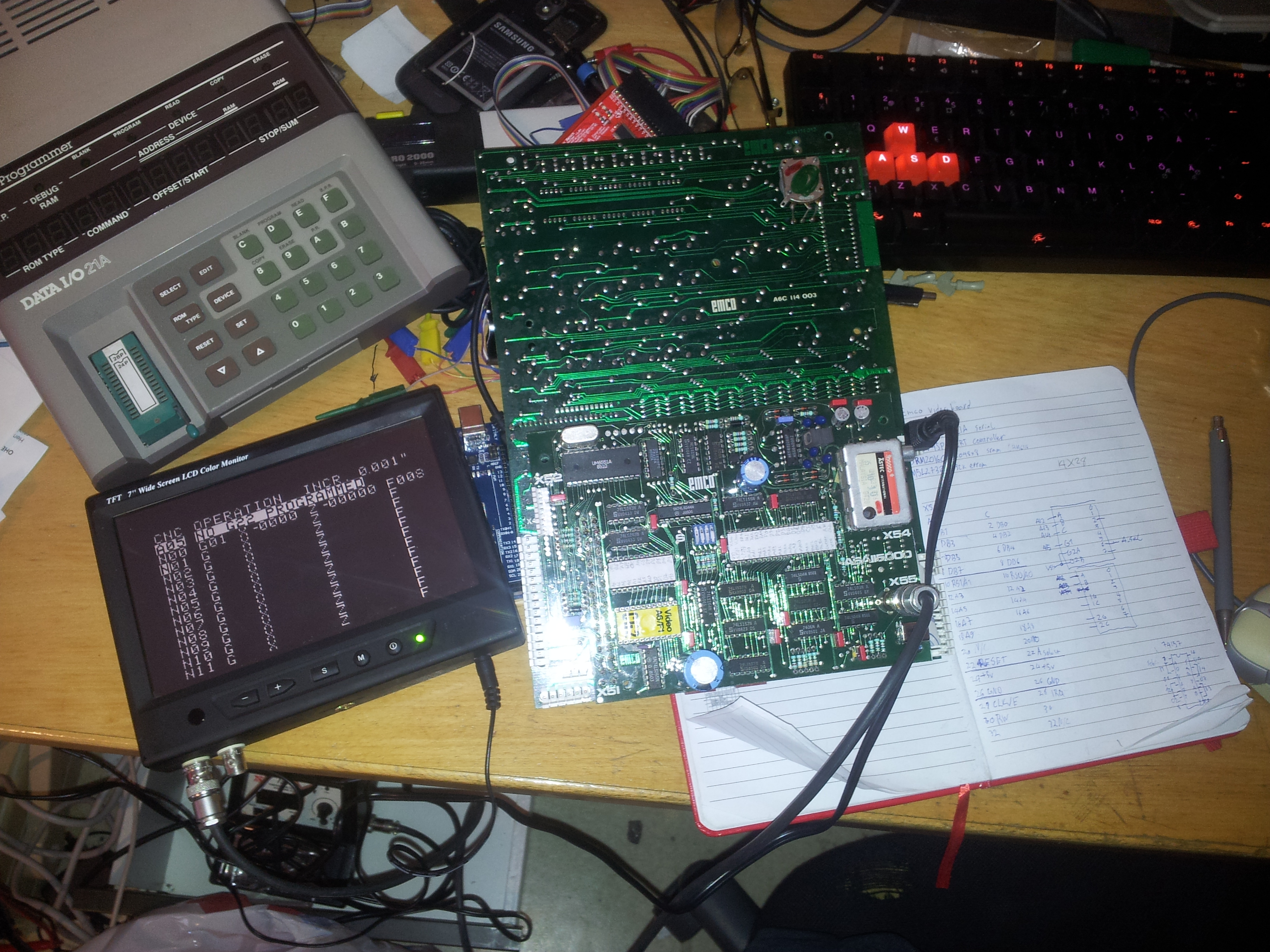 I got values of all the 15 register bytes. MC6845 CRTC datasheet had table for calculating these values from given timing and geometry. I just reversed formulas, and was able to determine that display was configured in 27×14 characters mode, and every character was 7 dots wide and 16 lines tall. Timing were otherwise normal for PAL tv, 50Hz frame rate and 15.625Hz horizontal sync. That gave just 224 active PAL lines, as CRTC was initialized in non-interlaced mode. I made handy excel workbook, that can be used to calculate values for MC6845 based systems.
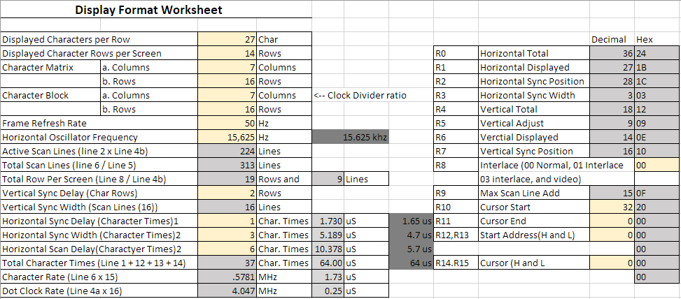
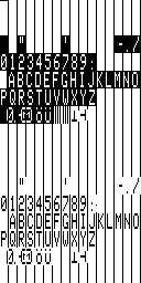
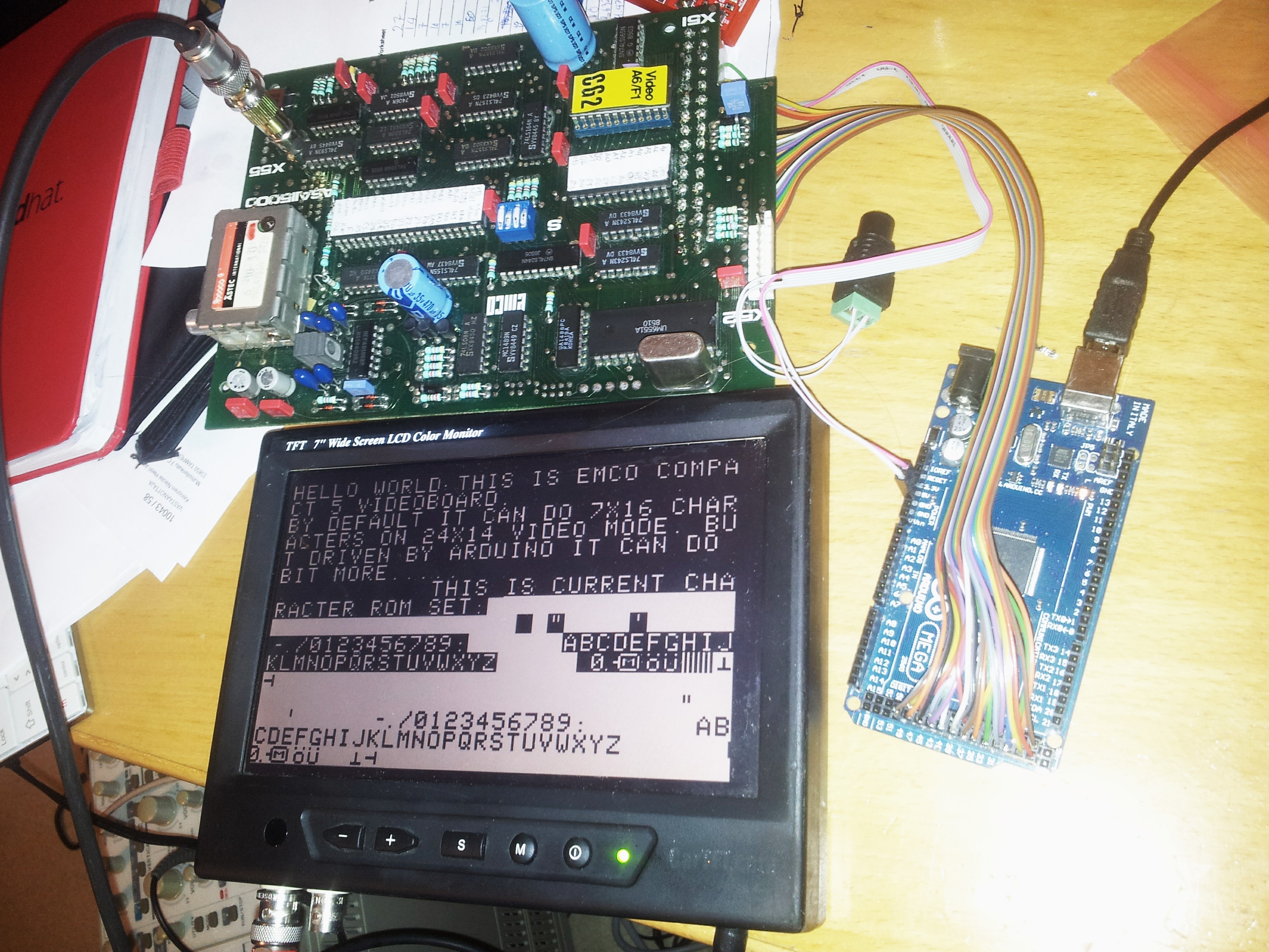 I connected video board to arduino, and made simple sketch that emulates CPU bus, and writes bytes into the CRTC registers and video RAM. Bus structure is quite simple; different ICs just have their own memory address range, where data can be written or read. Arduino then fills ram from text array and shows predetermined text on screen. I were able to push resolution up on modern LCD screen that shows overscan area and doesn’t need trace return times. Original character ROM is very limited, and only contains characters that are needed for CNC operation. Notice how bottom of character set just repeats inverted characters. Unlike CGA and other systems, Emco video controller is so simple that there isn’t any text effects. It would need addition hardware to underline and invert characters, so Emco opted to do inverting on character ROM. 256 character space is enough to do that, if charset is reduced just to minimal alphanumerical display.
I removed character ROM IC from board, and plugged it into old Data I/O 21A prommer. I was able to transfer data it contained to computer over serial link, and got binary rom dump. ROM layout is 2048×16 1-bit bitmap, that contains all 256 characters that are 8-bit wide. It was trivial to convert binary data to image file. Rightmost pixels of characters are ignored, as character clock is divided by 7 from pixel clock. Memory is still organized as 8×16 characters, so when converting to image there is black stripe at the end of every character. In display this is not shown, and is skipped.
For my purposes, original character set is too limited to display anything fun. It lacks even lowercase letters and most punctuation marks. Luckily, I have EPROM programmer on hand, and making and designing bitmap fonts is not that difficult. 7×16 font size is bit difficult to design, but doable. I made character set based on Apple II. First 31 characters are usually used as control characters and cannot be printed, but in many systems they contained some glyphs and symbols. I think these symbols became quite standard. I converted new character bitmap back to binary file, borrowed UV lamp so that I could erase original ROM, and then burned new content with prommer.
 Now I had bit more usable character set, that had all 256 unique ASCII characters. Also interesting note that characters are rendered closer to 1:2 ratio than 1:1. It would be possible to reduce characters to 8×8, and get double of vertical rows, and even more in interlaced mode, but text would be unreadable due low resolution of composite video signal. Maybe using MDA monitor and separate Hsync, Vsync and video line one could get much higher resolution out from this video board.
Here is iteration of arduino sketch I used to get text on display.
 //Data lines, Port A
#define DATAPORT_DIR DDRA
#define DATAPORT PORTA
#define D0 22 //PA0
#define D1 23
#define D2 24
#define D3 25
#define D4 26
#define D5 27
#define D6 28
#define D7 29 //PA7

//Lower address lines, Port C
#define L_ADRPORT PORTC
#define A0 37 //PC0
#define A1 36
#define A2 35
#define A3 34
#define A4 33
#define A5 32
#define A6 31
#define A7 30 //PC7

//Upper address lines, Port G
#define H_ADRPORT PORTG
#define A8  41 //PG0
#define A9  40
#define A10 39 //PG2
#define CS 38 //PD7 (CS decoding logic signal)

//Control signals for bus
#define ADR_SEL 43 //Enables write to video ram
#define E       45 //Data strobe, falling edge latches data
#define IRQ     42 //For serial, not used for video
#define RW      44 //Read/!Write, low signal enables write, high reads

//Memory addresses
uint16_t DipRead = 0x0100;
uint16_t CRTC_Adr = 0x0000;
uint16_t CRTC_Data =    0x0001;
uint16_t UART6551_Ctrl = 0x0200; //upto 0x0203
uint16_t VideoRAM_start = 0x0000;
uint16_t VideoRAM_end =   0x07FF;


enum CRTC_Register { //Registers for CRTC
  HorizontalTotal, HorizontalDisplayed, HSyncPosition, SyncWidth,
  VerticalTotal, VerticalTotalAdj, VercitalDisplayed, VSyncPosition,
  InterlaceMode, MaxScanLineAdr,
  CursorStart, CursorEnd, StartAdrH, StartAdrL, CursorH, CursorL
};

struct CRTC_RegisterValue {
  CRTC_Register address;
  uint8_t value;
};

void writeCRTCRegister(CRTC_Register address, uint8_t value) { //Writes register values to CRTC
  busWrite(address, CRTC_Adr);
  busWrite(value, CRTC_Data);
}

template <int N>
void writeCRTCRegisters(const CRTC_RegisterValue (&values)[N]) {
  for (int i = 0; i < N; i++) {
    writeCRTCRegister(values[i].address, values[i].value);
  }
}

CRTC_RegisterValue CRTC_Init[] = { //initial values for CRTC registers, 31x16 video mode with 7x16 font
  {HorizontalTotal,     0x74}, //HSync freq in character times, displayed characters + retrace - 1
  {HorizontalDisplayed, 0x50}, //Character displayed per line
  {HSyncPosition,       0x5C}, //Moves display left and right
  {SyncWidth,           0x08}, //Width of HSync and Vsync pulse
  {VerticalTotal,       0x12}, //Determines VSync frequency in character line times
  {VerticalTotalAdj,    0x09}, //Adjusts VSync frequency in fractions scan-line times
  {VercitalDisplayed,   0x0E}, //Character rows per display
  {VSyncPosition,       0x0E}, //Moves display up and down
  {InterlaceMode,       0b01}, //
  {MaxScanLineAdr,      0x0F}, //n. of scanlines per character row
  {CursorStart,         0x40}, //Cursor start scanline & blinkrate, 0x0*=non-blink 0x2*=non-display 0x4*=1/16blink 0x6*=1/32blink
  {CursorEnd,           0x0F}, //Last scanline of cursor
  {StartAdrH,           0x00}, //MA8-MA13 Start address of video RAM content shown on screen
  {StartAdrL,           0x00}, //MA0-MA7
  {CursorH,             0x00}, //Sets cursor position in video RAM, MA8-MA13
  {CursorL,             0x0B}, //MA0-MA7
};

CRTC_RegisterValue CRTC_28x15[] = { //initial values for CRTC registers, 30x16@50hz mode
  {HorizontalTotal,       39}, //HSync freq in character times, displayed characters + retrace - 1
  {HorizontalDisplayed,   28}, //Character displayed per line
  {HSyncPosition,         32}, //Moves display left and right
  {SyncWidth,              3}, //Width of HSync and Vsync pulse
  {VerticalTotal,         18}, //Determines VSync frequency in character line times
  {VerticalTotalAdj,      12}, //Adjusts VSync frequency in fractions scan-line times
  {VercitalDisplayed,     15}, //Character rows per display
  {VSyncPosition,         16}, //Moves display up and down
  {InterlaceMode,       0b00}, //00=progressive, 01=interlaced, 11= dual scan interlaced
  {MaxScanLineAdr,      0x0F}, //n. of scanlines per character row
  {CursorStart,         0x4B}, //Cursor start scanline & blinkrate, 0x0*=non-blink 0x2*=non-display 0x4*=1/16blink 0x6*=1/32blink
  {CursorEnd,           0x0F}, //Last scanline of cursor
  {StartAdrH,           0x00}, //MA8-MA13 Start address of video RAM content shown on screen
  {StartAdrL,           0x00}, //MA0-MA7
  {CursorH,             0x00}, //Sets cursor position in video RAM, MA8-MA13
  {CursorL,             0x00}, //MA0-MA7
};

void busWrite(uint8_t data, uint16_t address) { //Write data to spesific address
  DATAPORT_DIR = 0xFF;
  digitalWrite(RW, LOW);
  //write address
  L_ADRPORT = (address & 0xff);
  H_ADRPORT = (address >> 8);
  digitalWrite(E, HIGH);
  DATAPORT = data;
  delayMicroseconds(1);
  digitalWrite(E, LOW);
  delayMicroseconds(1);
}

uint8_t busRead(uint16_t address) { //Read data from spesific address, return data
  DATAPORT_DIR = 0x00;
  digitalWrite(RW, HIGH);
  L_ADRPORT = (address & 0xff);
  H_ADRPORT = (address >> 8);
  digitalWrite(E, HIGH);
  delayMicroseconds(1);
  digitalWrite(E, LOW);
  delayMicroseconds(10);
  uint8_t data = 0;
  data = DATAPORT;
  return data;
}

void setup() {
  DDRG = DDRC = 0xFF; //Set L Address as output
  //DDRG = 0x0F;      //Set U Address as output
  pinMode(E, OUTPUT);
  pinMode(ADR_SEL, OUTPUT);
  pinMode(IRQ, OUTPUT);
  pinMode(RW, OUTPUT);
  pinMode(CS, OUTPUT);
  digitalWrite(ADR_SEL, HIGH);
  digitalWrite(E, HIGH);
  digitalWrite(RW, HIGH);
  digitalWrite(CS, LOW);

  writeCRTCRegisters(CRTC_28x15); //Send initial register values to CRTC
  //writeCRTCRegister(CursorH, 0x01); //edit one value
  /*writeCRTCRegisters((CRTC_RegisterValue[])){ //edit multiple values
       {CursorH, 0x02},
       {CursorL, 0x00},
  */
  uint8_t dip = busRead(0x0100);
  uint8_t c = 0;
  digitalWrite(CS, HIGH );
  digitalWrite(ADR_SEL, LOW);

  for (uint16_t i = VideoRAM_start; i < VideoRAM_end; i++) { //clear videoram
    busWrite(32, i);
  }

  for (uint16_t i = 0; i < 255; i++) { //print character set
    busWrite(c, i + 28 * 15 * 2);
    c++;
    if (c == 0xFF) c = 0;
  }


  // char ascii[] = "**                          *** **                      ** ** ******              ****** **   *** ***        *** ***   ***   ***  **********  ***   ** *   ****    ****    ****   *  **  ****            ***   **    **                    **     ***                    ***   ***   ****        ****   ***  **      ***      ***      **  ***                      ***    ***                  ***         ***    ****    ***              **** **** ****                   ********               ";
  char ascii[] = "@H,                      ,s@@:s;,                  ,;s:GG ssssss,          ,ssssss GB  r93:,ss;,    ,;ss,:39r  @H2  ,99s ,;ssssss;, s9M,  HH #r ,HMG            #MH, :#, ,3s ,;;            ;;, s3,   ,#H                  H#,   sHH;  ::,        ,::  ;HHs ,2H   ,ssM2      HMss,   sS,,3s      :s      sr      s3,  ;ss:                :ss;      :ss;,   ,r;,   ,;ss:           ;ssr:HGGH::ss;,               ,;ssssss;,";
  for (uint16_t i = 0; i < sizeof(ascii) - 1; i++) {
    busWrite(ascii[i], i + 28 * 15 * 1);
  }


  char ruutu[] = {0xC9, 0xCD, 0xD1, 0xCD, 0xD1, 0xCD, 0xD1, 0xCD, 0xD1, 0xCD, 0xD1, 0xCD, 0xD1, 0xCD, 0xD1, 0xCD, 0xD1, 0xCD, 0xD1, 0xCD, 0xD1, 0xCD, 0xD1, 0xCD, 0xD1, 0xCD, 0xBB, 0x00,
                  0xBA, 0x31, 0xB3, 0x32, 0xB3, 0x33, 0xB3, 0x34, 0xB3, 0x35, 0xB3, 0x36, 0xB3, 0x37, 0xB3, 0x38, 0xB3, 0x39, 0xB3, 0x41, 0xB3, 0x42, 0xB3, 0x43, 0xB3, 0x44, 0xBA, 0x00,
                  0xC7, 0xC4, 0xC5, 0xC4, 0xC5, 0xC4, 0xC5, 0xC4, 0xC5, 0xC4, 0xC5, 0xC4, 0xC5, 0xC4, 0xC5, 0xC4, 0xC5, 0xC4, 0xC5, 0xC4, 0xC5, 0xC4, 0xC5, 0xC4, 0xC5, 0xC4, 0xB6, 0x00,
                  0xBA, 0x32, 0xB3, 0x41, 0xB3, 0x41, 0xB3, 0x41, 0xB3, 0x41, 0xB3, 0x41, 0xB3, 0x41, 0xB3, 0x41, 0xB3, 0x41, 0xB3, 0x41, 0xB3, 0x41, 0xB3, 0x41, 0xB3, 0x41, 0xBA, 0x00,
                  0xC7, 0xC4, 0xC5, 0xC4, 0xC5, 0xC4, 0xC5, 0xC4, 0xC5, 0xC4, 0xC5, 0xC4, 0xC5, 0xC4, 0xC5, 0xC4, 0xC5, 0xC4, 0xC5, 0xC4, 0xC5, 0xC4, 0xC5, 0xC4, 0xC5, 0xC4, 0xB6, 0x00,
                  0xBA, 0x33, 0xB3, 0x41, 0xB3, 0x41, 0xB3, 0x41, 0xB3, 0x41, 0xB3, 0x41, 0xB3, 0x41, 0xB3, 0x41, 0xB3, 0x41, 0xB3, 0x41, 0xB3, 0x41, 0xB3, 0x41, 0xB3, 0x41, 0xBA, 0x00,
                  0xC7, 0xC4, 0xC5, 0xC4, 0xC5, 0xC4, 0xC5, 0xC4, 0xC5, 0xC4, 0xC5, 0xC4, 0xC5, 0xC4, 0xC5, 0xC4, 0xC5, 0xC4, 0xC5, 0xC4, 0xC5, 0xC4, 0xC5, 0xC4, 0xC5, 0xC4, 0xB6, 0x00,
                  0xBA, 0x34, 0xB3, 0x41, 0xB3, 0x41, 0xB3, 0x41, 0xB3, 0x41, 0xB3, 0x41, 0xB3, 0x41, 0xB3, 0x41, 0xB3, 0x41, 0xB3, 0x41, 0xB3, 0x41, 0xB3, 0x41, 0xB3, 0x41, 0xBA, 0x00,
                  0xC7, 0xC4, 0xC5, 0xC4, 0xC5, 0xC4, 0xC5, 0xC4, 0xC5, 0xC4, 0xC5, 0xC4, 0xC5, 0xC4, 0xC5, 0xC4, 0xC5, 0xC4, 0xC5, 0xC4, 0xC5, 0xC4, 0xC5, 0xC4, 0xC5, 0xC4, 0xB6, 0x00,
                  0xBA, 0x35, 0xB3, 0x41, 0xB3, 0x41, 0xB3, 0x41, 0xB3, 0x41, 0xB3, 0x41, 0xB3, 0x41, 0xB3, 0x41, 0xB3, 0x41, 0xB3, 0x41, 0xB3, 0x41, 0xB3, 0x41, 0xB3, 0x41, 0xBA, 0x00,
                  0xC7, 0xC4, 0xC5, 0xC4, 0xC5, 0xC4, 0xC5, 0xC4, 0xC5, 0xC4, 0xC5, 0xC4, 0xC5, 0xC4, 0xC5, 0xC4, 0xC5, 0xC4, 0xC5, 0xC4, 0xC5, 0xC4, 0xC5, 0xC4, 0xC5, 0xC4, 0xB6, 0x00,
                  0xBA, 0x36, 0xB3, 0x41, 0xB3, 0x41, 0xB3, 0x41, 0xB3, 0x41, 0xB3, 0x41, 0xB3, 0x41, 0xB3, 0x41, 0xB3, 0x41, 0xB3, 0x41, 0xB3, 0x41, 0xB3, 0x41, 0xB3, 0x41, 0xBA, 0x00,
                  0xC7, 0xC4, 0xC5, 0xC4, 0xC5, 0xC4, 0xC5, 0xC4, 0xC5, 0xC4, 0xC5, 0xC4, 0xC5, 0xC4, 0xC5, 0xC4, 0xC5, 0xC4, 0xC5, 0xC4, 0xC5, 0xC4, 0xC5, 0xC4, 0xC5, 0xC4, 0xB6, 0x00,
                  0xBA, 0x37, 0xB3, 0x41, 0xB3, 0x41, 0xB3, 0x41, 0xB3, 0x41, 0xB3, 0x41, 0xB3, 0x41, 0xB3, 0x41, 0xB3, 0x41, 0xB3, 0x41, 0xB3, 0x41, 0xB3, 0x41, 0xB3, 0x41, 0xBA, 0x00,
                  0xC8, 0xCD, 0xCF, 0xCD, 0xCF, 0xCD, 0xCF, 0xCD, 0xCF, 0xCD, 0xCF, 0xCD, 0xCF, 0xCD, 0xCF, 0xCD, 0xCF, 0xCD, 0xCF, 0xCD, 0xCF, 0xCD, 0xCF, 0xCD, 0xCF, 0xCD, 0xBC, 0x00
                 };


  for (uint16_t i = 0; i < sizeof(ruutu) - 1; i++) {
    busWrite(ruutu[i], i + 28 * 15 * 3);
  }

  char text[] = "Hello World! This is EMCO Compact 5 videoboard.";
  for (uint16_t i = 0; i < sizeof(text) - 1; i++) {
    busWrite(text[i], i);
  }

  char text2[] = "By default it can do 7*16 characters on 24x14 video mode, but driven with Aarduino it can do bit more...";
  for (uint16_t i = 0; i < sizeof(text2) - 1; i++) {
    busWrite(text2[i], i + 60);
  }

  char text4[] = "This is current character rom set:";
  for (uint16_t i = 0; i < sizeof(text4) - 1; i++) {
    busWrite(text4[i], i + 191);
  }


  digitalWrite(ADR_SEL, HIGH);
  digitalWrite(CS, LOW );
}

uint16_t position = 0;
void loop() {
  // put your main code here, to run repeatedly:

  delay(5000);
  for (int i = 0; i < 28 * 15 * 1 + 1; i = i + 28) {
    writeCRTCRegisters((CRTC_RegisterValue[]) { //edit multiple values
      {StartAdrH, (i >> 8)},
      {StartAdrL, (i & 0xff)},
    });
    delay(50);
  }
  delay(5000);
  for (int i = 28 * 15 * 1  ; i < 28 * 15 * 2 + 1; i = i + 28) {
    writeCRTCRegisters((CRTC_RegisterValue[]) { //edit multiple values
      {StartAdrH, (i >> 8)},
      {StartAdrL, (i & 0xff)},
    });
    delay(50);
  }
  delay(5000);
  for (int i = 28 * 15 * 2 ; i < 28 * 15 * 3 + 1; i = i + 28) {
    writeCRTCRegisters((CRTC_RegisterValue[]) { //edit multiple values
      {StartAdrH, (i >> 8)},
      {StartAdrL, (i & 0xff)},
    });
    delay(50);
  }
  delay(5000);

  for (int i = 28 * 15 * 3; i >= 0; i = i - 28) {
    writeCRTCRegisters((CRTC_RegisterValue[]) { //edit multiple values
      {StartAdrH, (i >> 8)},
      {StartAdrL, (i & 0xff)},
    });
    delay(50);
  }
  //position = position + 30;
}
I have no definitive plans where to use this board. Initially I was thinking of text based video game console, but I have no time or great desire to make one. Or maybe I could borrow this design for video controller if I some day build retro computer. Anyway reverse engineering old video system was good challenge and exercise, and was good way to learn more about old CPU buses, video signaling and graphics generation.
Here is archive of all romdumps, schematics and fonts I used and made during reverse-engineering: Emco Compact
PS. I lied when I said it could not do graphics, it is possible using 7×16 pixels ;)

Hi,
This is such a great blog! I’m using your schematics to try and debug my video board for my compact 5. It powers up fine but I just get a solid white square output to my monitor.
I’m about to take it out and get it connected to an arduino to see if I can replicate what you’ve done to test it.
As it’s a solid white square, I am considering if it’s an issue with the dot clock circuit which is then giving a constant high luma output. Either that or the SRAM.
Thanks again!
Gareth
Dot clock is most likely running, as it is responsible for the overall timing of the video card. If the output is full screen white square, it could be character rom, video shift register or shift clock output. Either that, or the SRAM circuitry so that the video ram is giving constantly 0xFF output (or some other unused fully white character). If you have logic pen or oscilloscope, I would suggest checking 74 logic outputs and character rom data pins for activity. I have seen stuck gates and damaged roms that give constantly high output.
I am glad if my work helps somebody, and I hope you get your card fixed.
Hi Henri, this is a seriously impressive piece of work , well done . I have this board running in an Emco 5 CNC . I have, on the monitor ,rows of vertical lines running down the screen . I can send you a photo if you want. Any ideas on what would cause this? I can use the lathe but it just annoys me . Any help is welcome . I should say that I am a mechanical engineer so do struggle to follow some of your article . Many thanks Andrew
Hello,
You made a great work, the circuit diagram is very useful for me.
I made a new character ROM by mixing yours with the EMCO, now I can send lower case letters to the Compact5
to increase readability.
I use this for comments ( a header and 8 lines to display work piece name, raw dimensions, tools, spindle speed etc.) in the CNC file by modifying the original EMCO 6502 code.
Thanks for the font files.
Dieter
Wow, that is some dedication! Nice to see that people are still keeping these old controllers going. It’s nice to see that my work helped someone!
I built my own 6845 board, it took some tweaking to get it right, but yours looks pretty great! Excellent work reverse-engineering the board. I’ve done a few of these, and it’s like being drunk on punch – I love it. Anyway, best wishes and great job!
Joel
I need that card that Harwere
You sell it
?
Hi there,
Your project got my attention for 2 reason, the reverse of some old tech and the board itself.
I own a Emco Compact 5 lathe and I’m looking for this board. (my lathe did’nt have this option…)
If you are interested of selling it let me know.
Marc