Everybody knows old 78xx linear regulators. They are ok for many applications, but are problematic for bigger currents. They drop and regulate voltage smoothly for circuitry, but because all excess voltage are dissipate as heat, they are very inefficient. For my nixie clock I needed efficient little power supply for 5V rail, so I created this little baby:

Look how cute it is!
I used only parts I had in hand. Idea for this small board came when I found an AP1506 buck DC to DC converter from my part bin. Before you read this it could be good to get some background information about buck converters e.g. from wikipedia and read the AP1506 datasheet.
I followed preferred application circuit from datasheet, no need to reinvent wheel :). All parts are recycled from other devices. I used equation 5V = 1.23V * (1+ 1.5KΩ/R1) which gives roughly 4.5KΩ for R1. Precision worm drive type potentiometer for adjusting feed back voltage were used in place of R1. 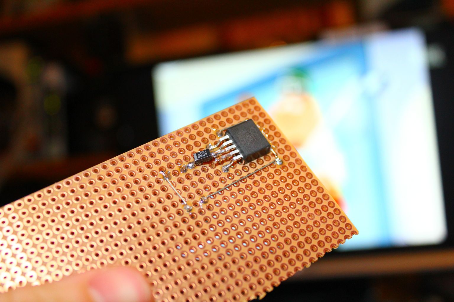
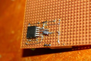
IC soldered to veroboard. Notice to bent up legs, spacing is not right, but with only 3 leg down I managed to get all of them to contact only one pad. Earthing is done circular as I often do. Also important schottky diode is soldered underside, little bit awkward soldering, but this is only prototype. 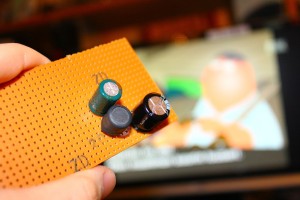
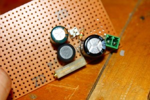
And first components I came up. 2x 1000µF electrolyte caps and inductor which should be 30-50µH, I don’t have inductance meter, but circuit works, so I hope it is correctish. Caps are from bottom of my bin of 1000 and 1 parts, so they also can be out of shape. It could be smart to add some smaller caps to eat hi-freq noise away.
Enjoy from the shallow depth of focus x3
It actually works! This is my first switching mode supply if joule thief I built couple years ago is not counted in. I know that layout is not even near the optimal, parasitic capacitances and couplings here an there. And component values and characteristic are bit mysterious. My measurements anyway show that this little board is pretty good actually. Lets take equipment out, shall we?
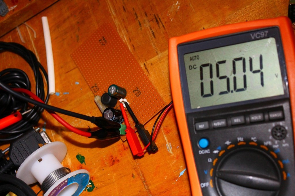
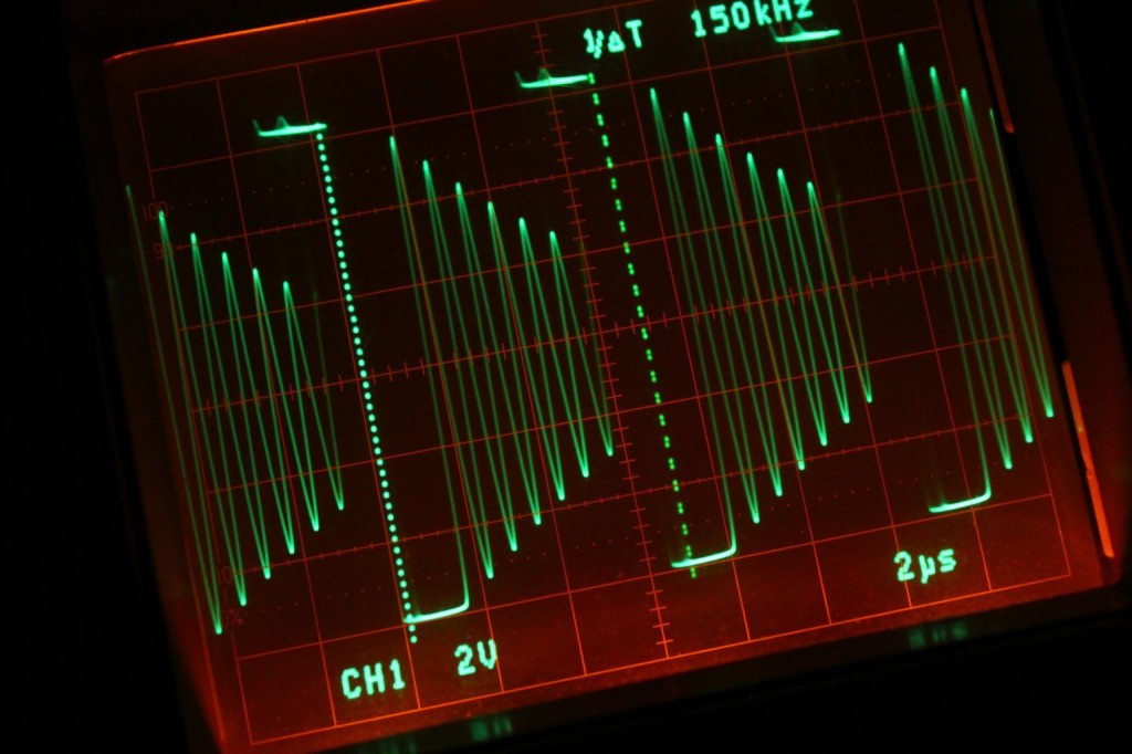
It gives nice 5V out, and takes 9-22V in. But this tells not much. Ripple is 0.015V measured with DMM. “Holy waveform, Batman! We need an oscilloscope”
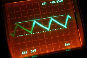
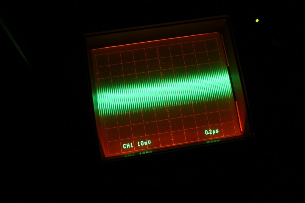
Without load the output is like saw, but when load is applied it was much smoother, but had still 10mV or so ripple, not too bad, I have seen much worse ripples in my computer PSU.
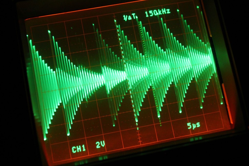
Picture is not skew, your eyeballs are just in angle. This is from output pin before the inductor. 150kHz as promised. I am not completely sure if this should not look like this…
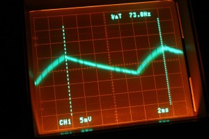
After applying load. This is much nicer and output is still steady 5V
Don’t you just love that scope screen
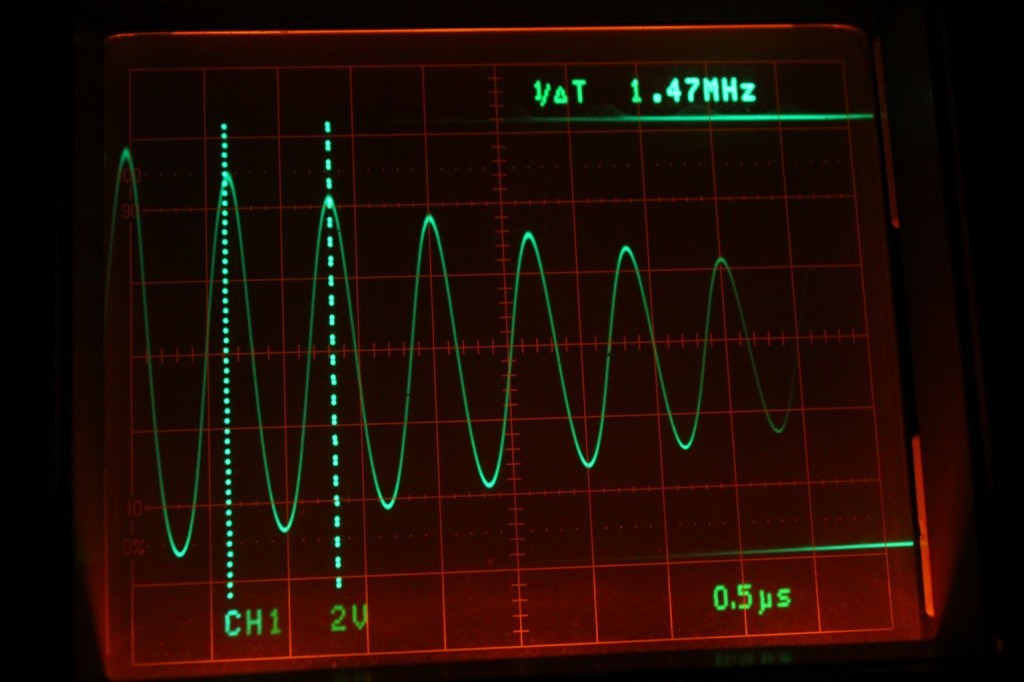
- Hmm. Interesting. Some kind of ringing?
Maybe I dare to connect this to my nixie clock. Eyes closed and fingers crossed I switch 12V output on. No sound of arcing? No blue smoke O.o What the smeg it is working just as it should be. I cant believe.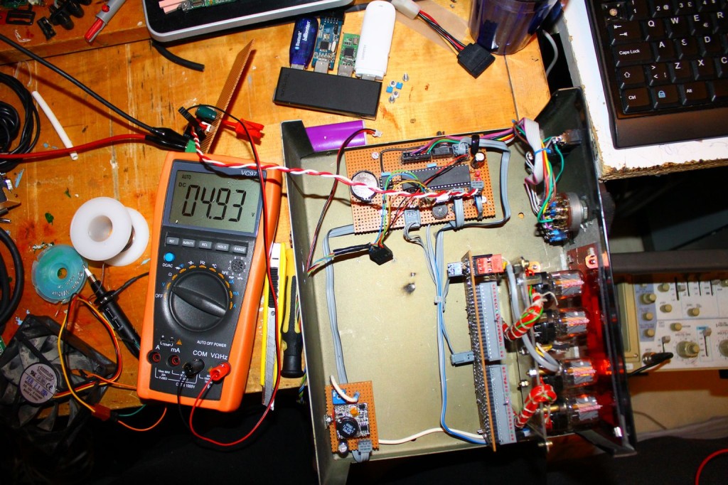
Voltage is bit low, but that can be fixed by turning R1 couple turns. Clock worked as when feed by 5V from bench supply. There was not glitches even though I connected and disconnected it many times and even alarm sound played right, so no marks of AVR picking wrong clock cycles or interrupts from 5v lane.
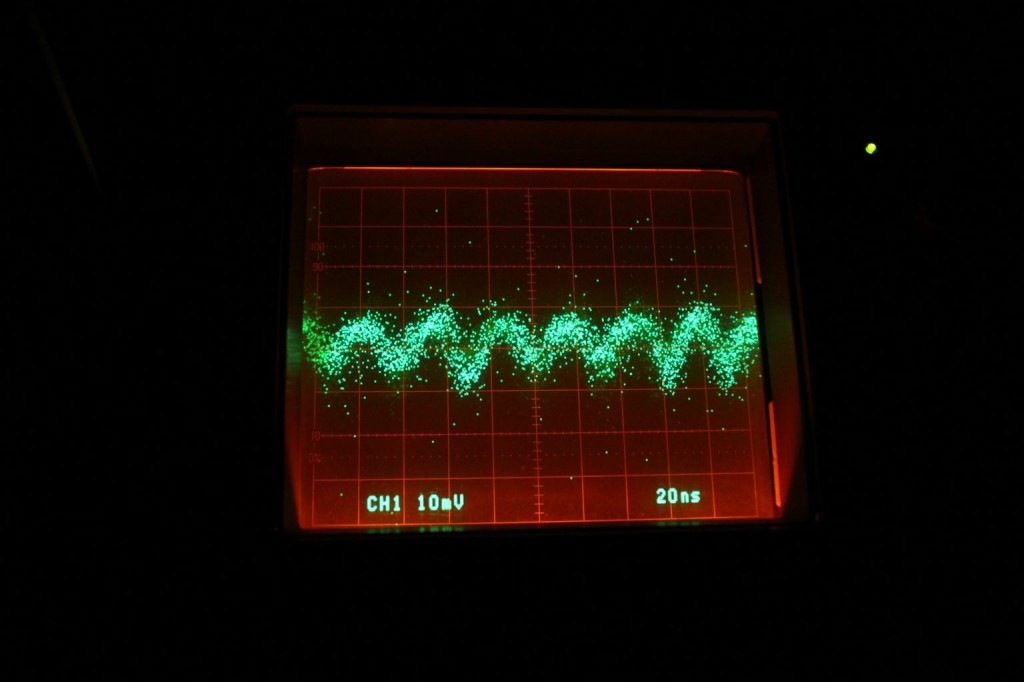
My oscilloscope have sampling function which sort of works
Some noise, but I think it not mater
Next thing is sawing that board smaller, and making vertical stands. Then wiring and making proper power connector to backplate. Fuse could also be very good addition, I don’t want blow anything.
And if you wonder, nixie clock takes 355mA and my little buck converter takes 157mA in. So eff=(Uout*Iload)/(Uin*Iin)=(4.95V*0.355A)/(12.14V*0.157A) ≈ 92% which is amazing efficiency for circuit built from obscure components to veroboard without thinking of construction.