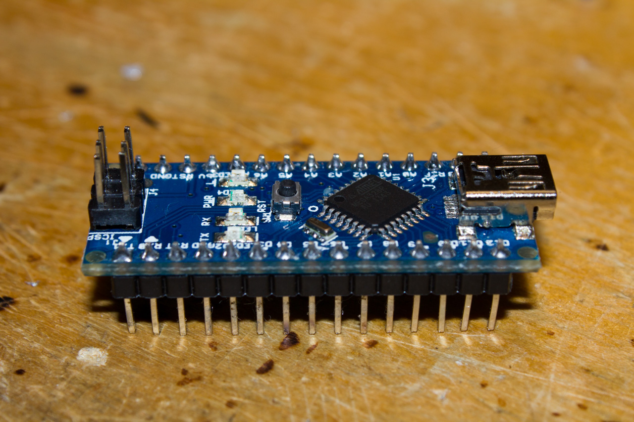
 Apparently I’m not the only one that have had problems with a Arduino (clone) nano’s USB connection. Usually it works ok but sometimes, particularly when an external power input is used, a FTDI chip inside the Arduino does not want to be detected by computer. This is bug made by the original Arduino developers to their schematics, and can be easily fixed afterwards if there is odd troubles with it.
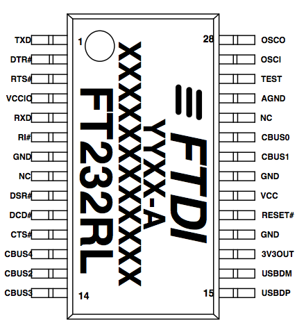
This fault is due one missing connection. The FTDI FT232’s datasheet says that pin named TEST must be connected to ground, or otherwise it will not work properly.

Page 7, Table 3.3 Miscellaneous Signal Group
So why the Arduino group does not have connected that TEST signal to ground? Who knows… Maybe it is a bug, oversight or misconception. FTDI clearly shows how their chip should be connected in multiple cases in their datasheets application notes.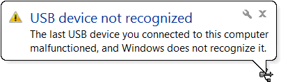
So if you get these “USB device not recognized” in windows, or if your console fills up with USB error messages in *nix systems when connecting the Arduino it is not you, it is the Arduino. If the TEST signal pin is not tied down, it seems that the FTDI FT232 usb-to-serial converter goes in some bizarre testing mode (hence the name for the pin) if it floats up during USB handshake.
 Conveniently there is a ground pin just next to the TEST pin. Actually it is an Analog GND, not the same thing as GND, but I measured them to be connected together. Better than nothing even though it may broke some design rules. Usually Digital GND and Analog GND should be separated as much as possible, and only have single short route between them to stop ground loops.
 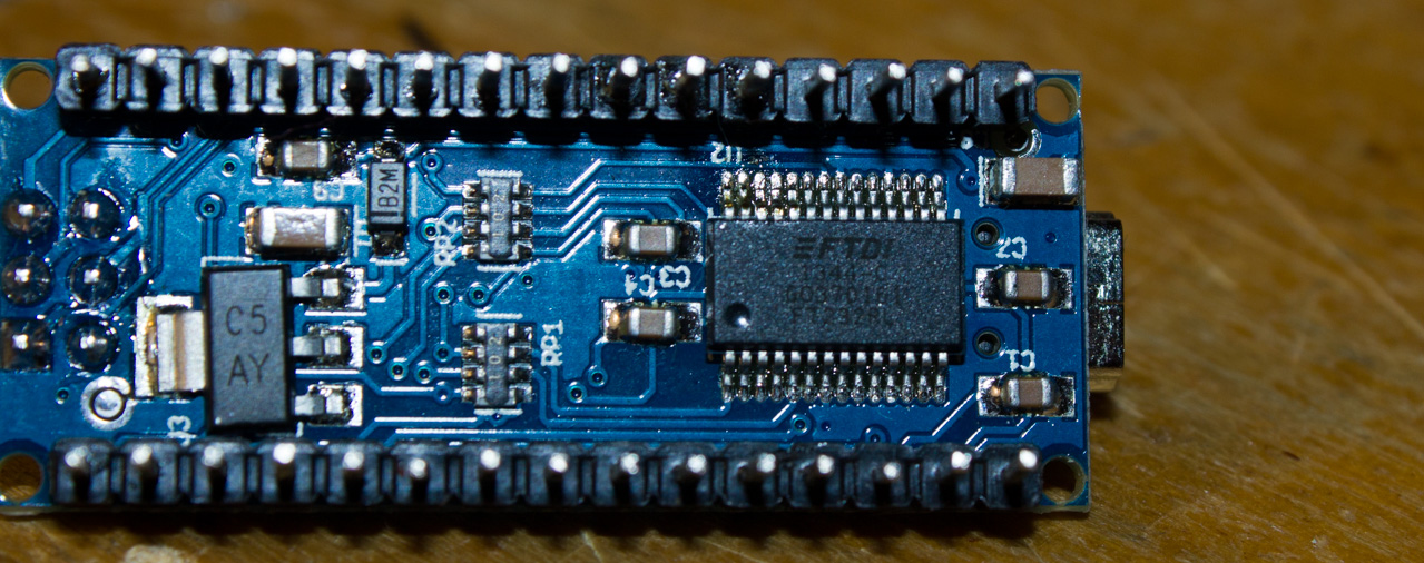 Here is underside of the Arduino Nano board. Or I should say a clone of it. Chinese have done good work copying the original design, so far that they have included same faults that bugs the real Arduino Nano. Anyway 26. TEST pin have left floating, not connected to anything. Pins 26 and 25 can be bridged by soldering them together. This should tie the TEST signal to ground and prevent the chip from going to the test mode.
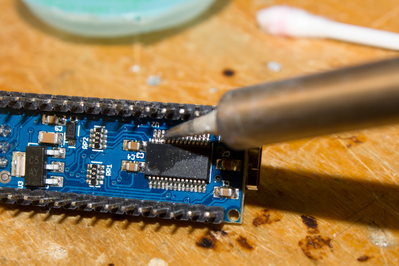 Touch touch 3th and 4rd IC pins from the left with a hot wet soldering iron tip. You need to bridge these pins together. Be careful not to solder any other pins or damage the Arduino otherwise.
 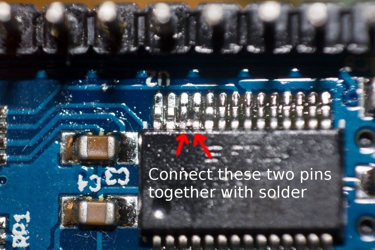 Notice which two pins have solder between them. You should check connection with multimeter. This fix needs some good eye-hand coordination as parts are kinda tiny. Pin pitch in this package is only 0.65mm.
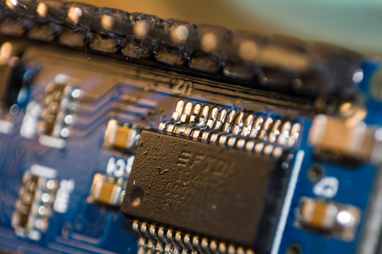
 Connecting the TEST signal to the ground fixed all problems that I had with USB. Now the Arduino is detected every single time it is connected to USB device. Even my Android phone now detects and shows FTDI chip. This problem may have gone unnoticed because when the Arduino is powered from the USB port, it usually connects without problem. But if power and ground connections are formed in wrong order, or the Arduino is already powered when the USB connection is made, it is left unrecognized by USB host.
I hope this article helps you in case of this same bug that may or may not appear randomly.
Thanks!
Wow! It worked, thank you so much!!
I appreciate your effort to write this fix
This work needs detail, but it is possible and it works wonders
If you are thinking about it, stop and just do it!
how to solder for ch340g please… what are the pins to be soldered
This fix does only apply to FTDI serial chip on clone arduino boards. For CH340G I do not have fix as I have had no problems with it. Maybe the chip is faulty or fake copy that does not work at all (yes, there are even copies and relabeled broken fakes of cheap chinese ICs).
i will try this and give a comment to you.ok!
Allah razı olsun kardeş :D
That is a fix i have been waiting for for a long time.. Many thanks
Thank you so much!
You safe my life!!! Thanks
wow! bulls eye!..Thanks
Wow. My nano was unrecognized every time–windows and Linux. This is the fix!
Perfect, it works. Pretty difficult to solder though, make sure to have some solder wick ready.
Great fix ! Worked fine for me
Great! thanks a lot: this fix works for me 100%!