Hello, I’m Ketturi Fox, and I’m addict. Yes, I have VFD addiction, Vacuum Fluorescent Displays, I mean. I have big box of them, waiting for appropriate project (which probably will never come). This time I found big nice displays from old digital scale.
 So I hauled my catch to home. Whole machine was far to heavy, and I couldn’t open it without allen key. Pity I can’t now power it up, because main logic, power supply and keyboard&printer are missing. Reverse engineering will also be harder.
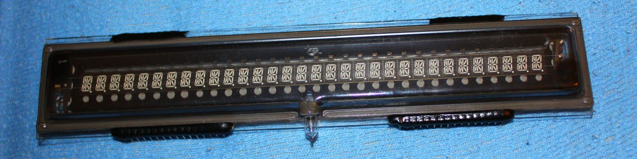
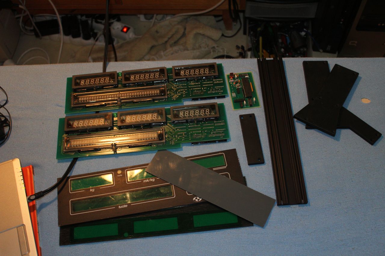
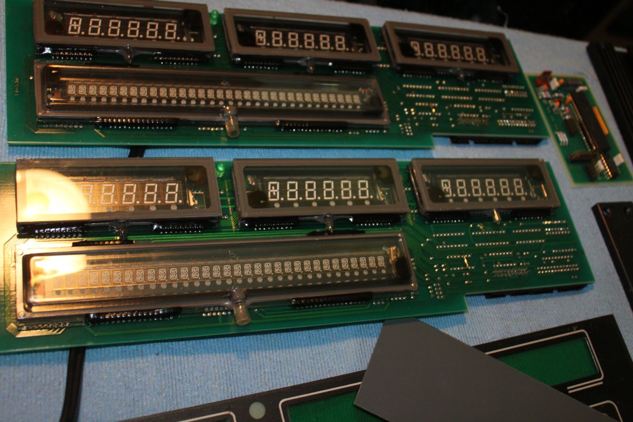 3x 6 digit ones, and one 32 digit 14 segment alphanumeric displays on each board. Small board is keyboard controller with old Intel 8-bit microcontroller. Display board both have their own processors and support logic, and all were connected together with daisy chain ribbon cable. Probably 8-bit parallel line.
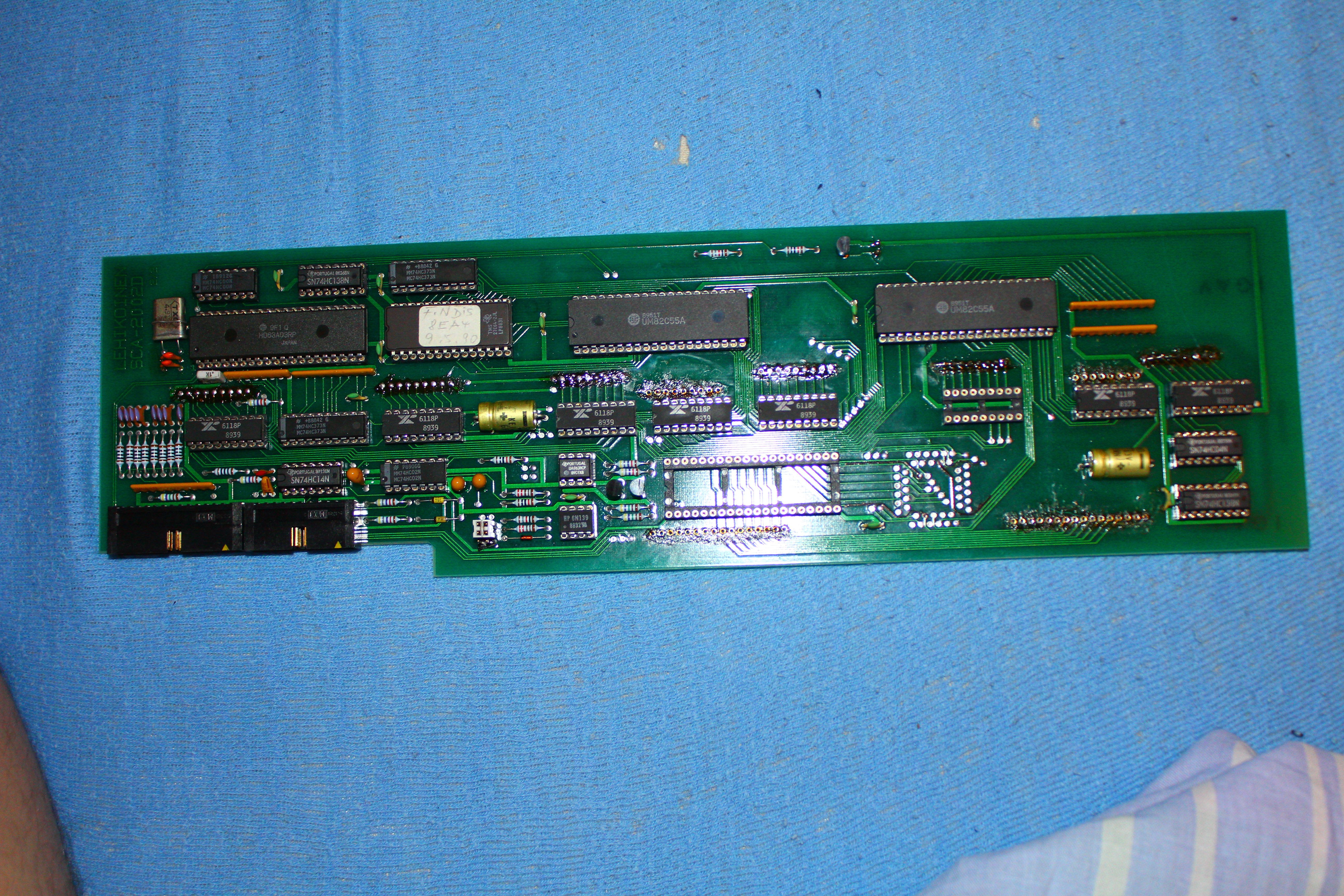
Here is bottom view. From upper left there is HD63A03R MCU and ROM and couple of interface IC’s. Small IC’s are some support logic chips and 6118 VFD buffer drivers. Big missing IC is SN75518, 32 line VFD driver with internal shift register.
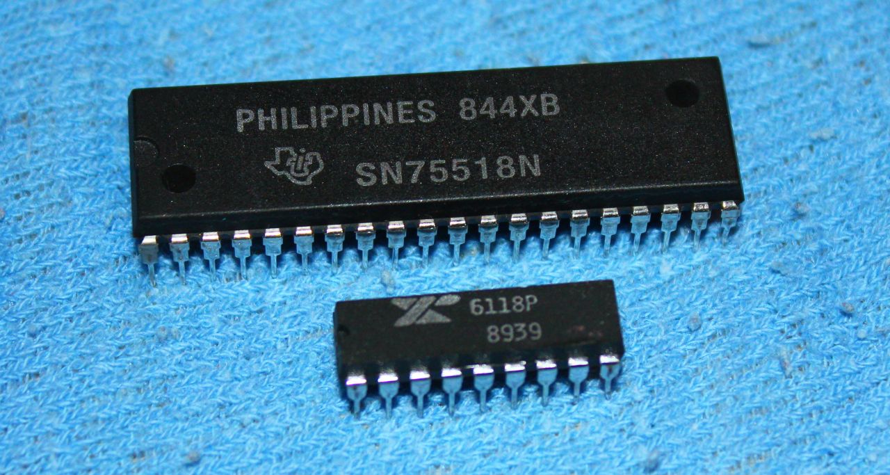 These black centipedes are important, I will use these for new build, and replace old processor with modern AVR. I have idea use the big alphanumeric display for showing new RSS feed and email tittles.
 Modules unsoldered. I destroyed 2 of smaller displays, glassware should be handled with care. I was more carefully with big one, and managed to remove it one piece. I did not touch to other display board, for good reason :P
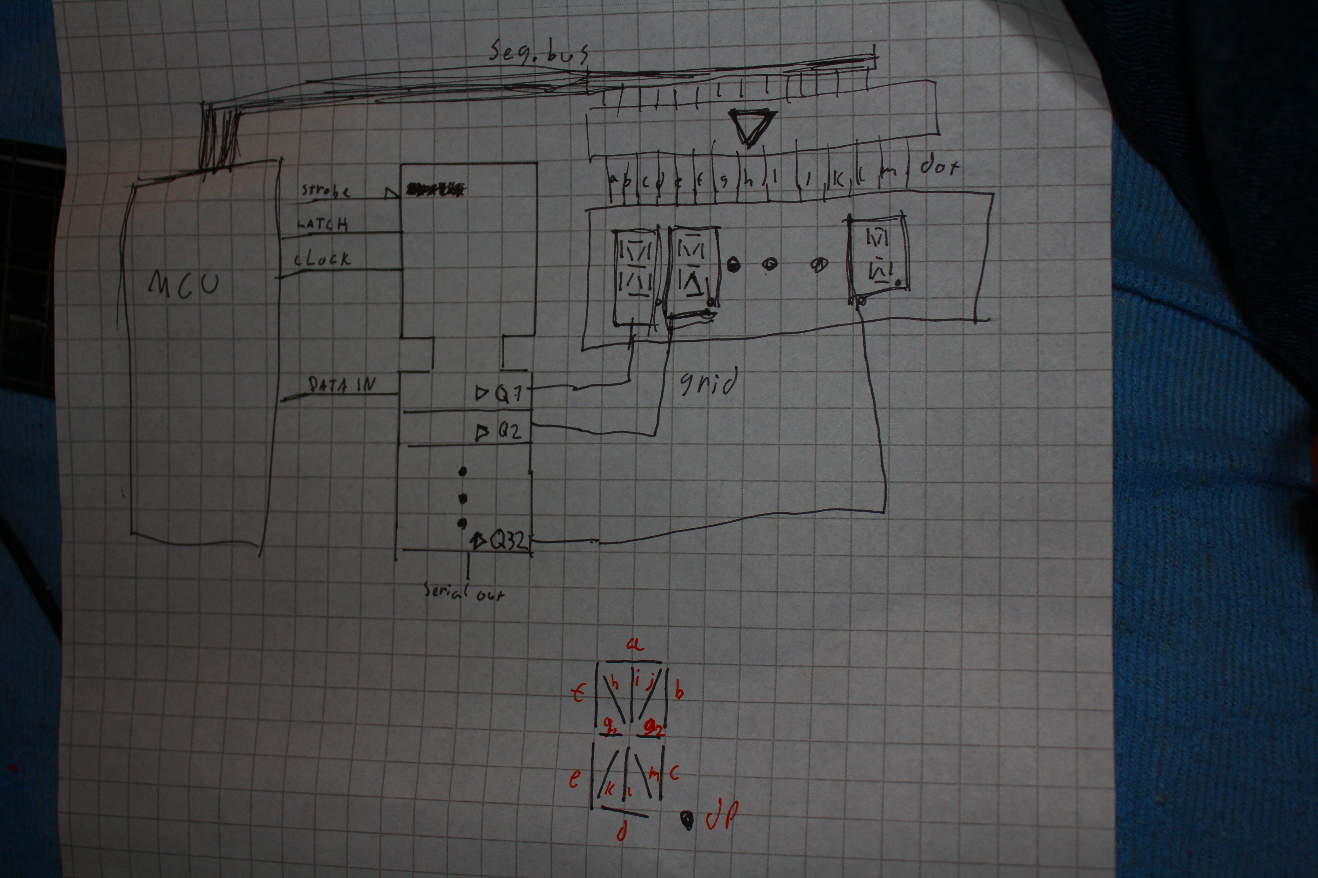 Quick schemasketch. SN75518 6118 Datasheets for driver ICs. Now I need to make power supply, which gives about 45V grids/segs and 3V for filament.
Can I replace the 6118 with a Boost Converter like the XL6009?
I don’t think so, as they are doing very different tasks. You can use boost converter to generate voltages to drive whole display, but 6118 IC is just for switching voltage on and off for different digits of VFD display. You can think 6118 as bank of multiple transistors, when you put 5 volts into input pin, high voltage from Vbb pin is connected to output pin.
I got no answer!!
Sorry, I had missed new comments. Yes, you connect SN75518 data lines to Arduino and drive it like any other shift register. Then you can connect SN75518 outputs to VF display, and connect 5V from arduino to VCC1 pin and 15-30V for VFD drive voltage to VCC2 pin. In addition you need couple volts for filament in VFD.
Thank you very much
Hi, my friend, one more question: should the Data, Strobe, Latch and Clock pins be declared in the code? Would you have a sample code for me? Sorry for my ignorance on the subject! Thanks ++
Yes, they need to be declared. With Arduino, you can follow https://www.arduino.cc/en/tutorial/ShiftOut this guide. You can keep Strobe pin always low for testing. Strobe is used only to set display blank while updating data so it will not flicker. I do not have sample code for arduino. I have old code for this project that is written for AVR-GCC here: https://pastebin.com/xUHmwcRN but it would not work straight without some large edits.
But it’s a simple statement like:
int latchPin = 8;
int clockPin = 12;
int dataPin = 11;
Before setup()?
Thanks++
Yes, then you can use something like digitalWrite(latchPin, HIGH); on arduino to change that pin output. But you can also just use digitalWrite(8, HIGH); to do same job, it is just easier to read code that uses aliases so you don’t have to look up every time what pin 8 does.
Hi friend! I have a question:
I simply connect the SN75518 to the VFD and Arduino logically with the Power Supply? Thank you
Greetings from Australia,
would you care to sell me 1 (or more) of the larger 32 character displays?
Sorry, I am not sure if I still even have those units (I had only two of them), and shipping them would be ridiculously expensive, it would be over 60€ + taxes. You probably have much better luck by trying to find similar display units from ebay or other online auction sites.
Your not the only one addicted to these things. I have 2 paper shipping boxes filled with various VFD stuff.