I have yet published basic schematics and code for display project. 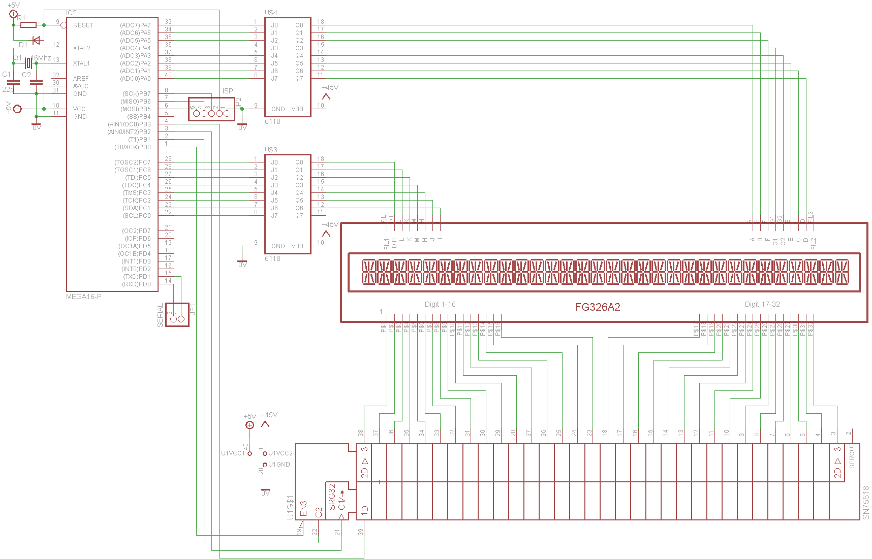 Atmega 16 work as display controller. It will read data from uart serial port, place it to text buffer and simultaneously multiplex display trough segment voltage buffers and huge digit shift register. ASCII text is converted to segment data and font can be created with computer program.
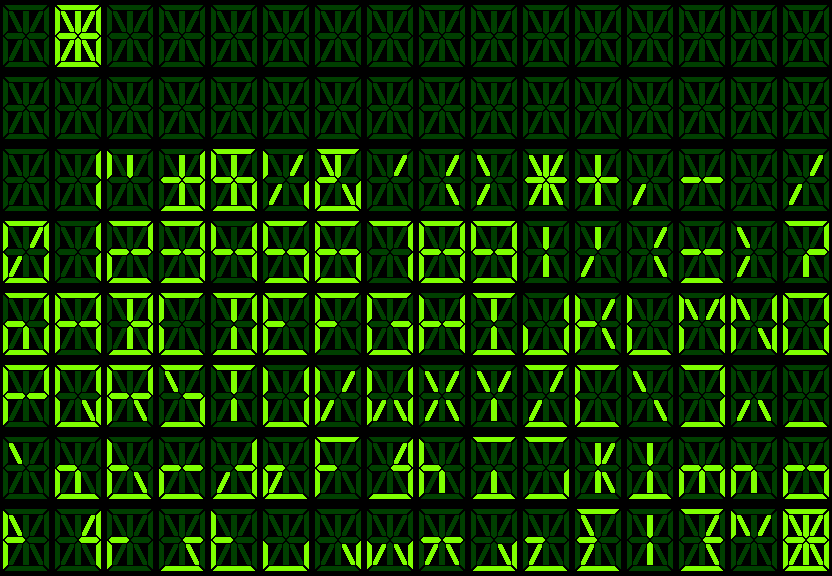 My friend made quick program, which converts png font file to C array cleverly taking one pixel from segment and determining if color value is bright green. Writing font otherwise would have been boring and unintuitive. Small letters look bit weird, as this is only 14 segment display. 16 segment display with binomial top&bottom segments would be better. I may just use upper case letters but for compatibly I made all of them. I will also implement some ASCII control charters to clear screen, move cursor and to make audible bell and turn on/off led. I have incomplete code for multiplexing and font generation. UART communication is not working at all, an I can’t figure why I can’t get other than broken charters. I have tried with different baudrates, tried to calculate UBRR0 manually, changed clock crystals to specific uart ones, and still can’t get it work. Either my AVR or serial -> bluetooth adapter or FTDI usb cable are broken or something. Anyway work-in-progress code here:
/* Ketturi Fox 2013
 * File:	main.c
 * Project: VFD Driver
 * Project folder: https://www.dropbox.com/sh/24stwfan7eqthdz/DxebGKKUiF
 *
 */

//02.09.13 Edit: one zero missing, these should be 16000000UL 16Mz,
//not 1600000UL 1.6Mhz
#ifndef F_CPU
//#define F_CPU 1843200UL // 18.432 Mhz
#define F_CPU 1600000UL // 16 Mhz
#endif

  #define BAUD 19200 //UART baud rate, 19200 works with 16Mhz clock
  #include <util/setbaud.h>

#include <inttypes.h>
#include <stdint.h>
#include <avr/io.h>
#include <avr/interrupt.h>
#include <avr/pgmspace.h>
#include <util/delay.h>

// Macros for bit manipulation
#define SET_BIT(target, bit) ((target) |=   _BV((unsigned char) (bit)))
#define CLR_BIT(target, bit) ((target) &= ~(_BV((unsigned char) (bit))))

#define DISPLAY_SIZE 32 //digits
#define LONG_DELAY  450 //Delays for multiplexing
#define SHORT_DELAY  50 //need to be made interrupts/something useful during delays

/*
* Font for segments
* generated with kukkafontti by magnificent hauvakukka
*/
// First byte  == PORT_A
// Second byte == PORT_C
//{ (d,c,e,g2,g1,f,b,a),(n/c,i,j,h,m,k,l,dp) },
// ASCII, control charters not handled here, only for reference
//some charters, like 1-5 need to be re-purposed as ä,ö,Ä,Ö and forwarded from 132, 148, 142, 153
//handling d.p. should be rethough, now it leaves empty charter left to it
//darn I love ASCII <3
const unsigned char font[128][2] = {
	{ 0b00000000, 0b00000000 }, //NUL Null \0 ^@      (null charter, but shows as empty block dunno)
	{ 0b11111111, 0b01111111 }, //can be used like test charter lighting all segments
	{ 0b00000000, 0b00000000 },
	{ 0b00000000, 0b00000000 },
	{ 0b00000000, 0b00000000 },
	{ 0b00000000, 0b00000000 },
	{ 0b00000000, 0b00000000 }, //ACK Acknowledge     (send for data successfully received)
	{ 0b00000000, 0b00000000 }, //BEL  Bell \a ^G     (make audible notification for email etc)
	{ 0b00000000, 0b00000000 }, //BS Backspace \b ^H  (remove last charter from textBuffer)
	{ 0b00000000, 0b00000000 },
	{ 0b00000000, 0b00000000 }, //LF Linefeed \n ~J   (clear textBuffer)
	{ 0b00000000, 0b00000000 },
	{ 0b00000000, 0b00000000 }, //FF Formfeed \f ^L   (clear textBuffer, for compatibly)
	{ 0b00000000, 0b00000000 }, //CR Carriage return \r ^M (Return "cursor" to first digit)
	{ 0b00000000, 0b00000000 },
	{ 0b00000000, 0b00000000 },
	{ 0b00000000, 0b00000000 },
	{ 0b00000000, 0b00000000 }, //DC1 Device control (Turn leds on/off or sumthing)
	{ 0b00000000, 0b00000000 }, //DC2
	{ 0b00000000, 0b00000000 }, //DC3
	{ 0b00000000, 0b00000000 }, //DC4
	{ 0b00000000, 0b00000000 }, //NAK neg. acknowledge (Houston, we have problem)
	{ 0b00000000, 0b00000000 },
	{ 0b00000000, 0b00000000 },
	{ 0b00000000, 0b00000000 },
	{ 0b00000000, 0b00000000 },
	{ 0b00000000, 0b00000000 },
	{ 0b00000000, 0b00000000 }, //ESC Escape \e ^[     (dunno, not needed)
	{ 0b00000000, 0b00000000 },
	{ 0b00000000, 0b00000000 },
	{ 0b00000000, 0b00000000 },
	{ 0b00000000, 0b00000000 },
	{ 0b00000000, 0b00000000 }, //" " space or empty block
	{ 0b01000010, 0b00000001 }, //"!"
	{ 0b00000100, 0b01000000 },
	{ 0b11011010, 0b01000010 },
	{ 0b11011101, 0b01000010 },
	{ 0b01000100, 0b00101000 },
	{ 0b11101001, 0b01010100 },
	{ 0b00000000, 0b00100000 },
	{ 0b00000000, 0b00100100 },
	{ 0b00000000, 0b00011000 },
	{ 0b00011000, 0b01111110 },
	{ 0b00011000, 0b01000010 },
	{ 0b00000000, 0b00001000 },
	{ 0b00011000, 0b00000000 },
	{ 0b00000000, 0b00000001 }, // "."    (light dot in display)
	{ 0b00000000, 0b00101000 },
	{ 0b11100111, 0b00101000 },
	{ 0b01000010, 0b00000000 }, //"0"
	{ 0b10111011, 0b00000000 },
	{ 0b11011011, 0b00000000 },
	{ 0b01011110, 0b00000000 },
	{ 0b11011101, 0b00000000 },
	{ 0b11111101, 0b00000000 },
	{ 0b01000011, 0b00000000 },
	{ 0b11111111, 0b00000000 },
	{ 0b11011111, 0b00000000 },
	{ 0b00000000, 0b01000010 }, //"9"
	{ 0b00000000, 0b01001000 },
	{ 0b00000000, 0b00100100 },
	{ 0b10011000, 0b00000000 },
	{ 0b00000000, 0b00011000 },
	{ 0b00010011, 0b00000011 }, //"?"
	{ 0b11101011, 0b00000010 },
	{ 0b01111111, 0b00000000 }, //"A"
	{ 0b11010011, 0b01000010 },
	{ 0b10100101, 0b00000000 },
	{ 0b11000011, 0b01000010 },
	{ 0b10101101, 0b00000000 },
	{ 0b00101101, 0b00000000 },
	{ 0b11110101, 0b00000000 },
	{ 0b01111110, 0b00000000 },
	{ 0b10000001, 0b01000010 },
	{ 0b11100010, 0b00000000 },
	{ 0b00101100, 0b00100100 },
	{ 0b10100100, 0b00000000 },
	{ 0b01100110, 0b00110000 },
	{ 0b01100110, 0b00010100 },
	{ 0b11100111, 0b00000000 },
	{ 0b00111111, 0b00000000 },
	{ 0b11100111, 0b00000100 },
	{ 0b00111111, 0b00000100 },
	{ 0b11010001, 0b00010000 },
	{ 0b00000001, 0b01000010 },
	{ 0b11100110, 0b00000000 },
	{ 0b00100100, 0b00101000 },
	{ 0b01100110, 0b00001100 },
	{ 0b00000000, 0b00111100 },
	{ 0b00000000, 0b00110010 },
	{ 0b10000001, 0b00101000 }, //"Z"
	{ 0b10100101, 0b00000000 },
	{ 0b00000000, 0b00010100 },
	{ 0b11000011, 0b00000000 },
	{ 0b00000000, 0b00001100 },
	{ 0b10000000, 0b00000000 },
	{ 0b00000000, 0b00010000 },
	{ 0b10101000, 0b00000010 }, //"a"
	{ 0b10101100, 0b00000100 },
	{ 0b10111000, 0b00000000 },
	{ 0b11010010, 0b00001000 },
	{ 0b10101000, 0b00001000 },
	{ 0b00101101, 0b00000000 },
	{ 0b11010010, 0b00100000 },
	{ 0b00101100, 0b00000010 },
	{ 0b00000000, 0b00000010 },
	{ 0b11000010, 0b00000000 },
	{ 0b00000000, 0b01100110 },
	{ 0b00100100, 0b00000000 },
	{ 0b01111000, 0b00000010 },
	{ 0b00101000, 0b00000010 },
	{ 0b11111000, 0b00000000 },
	{ 0b00101100, 0b00010000 },
	{ 0b01010010, 0b00100000 },
	{ 0b00101000, 0b00000000 },
	{ 0b10010000, 0b00000100 },
	{ 0b10101100, 0b00000000 },
	{ 0b11100000, 0b00000000 },
	{ 0b01000000, 0b00000100 },
	{ 0b01100000, 0b00001100 },
	{ 0b00011000, 0b00001100 },
	{ 0b11000000, 0b00000100 },
	{ 0b10001000, 0b00001000 }, //"z"
	{ 0b10001001, 0b00011000 },
	{ 0b00000000, 0b01000010 },
	{ 0b10010001, 0b00100100 },
	{ 0b00000100, 0b00110000 },
	{ 0b11111111, 0b01111110 } //DEL    (also not needed, ignored charter"
};

/*
 * Port & device init
 */
void boot(void) {
	// Set port directions and pull-ups
	DDRA = 0b11111111;
	DDRC = 0b11111111;
	DDRB = 0b00001111;
}

void WriteMultiplexBit(int bit]{
/* Siftregister configuration:
*Strobe (outputs enabled) PB0
*Latch enable (Latch clock) PB1
*Clock PB2
*Data In PB3
*
*Data is entered with L -> H clock edge
*While Latch Enable is H, Data -> Outputs
*Strobe puts outputs on when L. (can be tied to L)
*/

#define Strobe_PORT 	PORTB
#define Latch_PORT		PORTB
#define Clock_PORT		PORTB
#define Data_PORT		PORTB

#define Strobe_BIT		0
#define Latch_BIT		1
#define Clock_BIT		2
#define Data_BIT		3

	#define SET_Strobe ((Strobe_PORT) |= _BV(Strobe_BIT))
	#define CLR_Strobe ((Strobe_PORT) &= ~(_BV(Strobe_BIT)))

	#define SET_Latch ((Latch_PORT) |= _BV(Latch_BIT))
	#define CLR_Latch ((Latch_PORT) &= ~(_BV(Latch_BIT)))

	#define SET_Clock ((Clock_PORT) |= _BV(Clock_BIT))
	#define CLR_Clock ((Clock_PORT) &= ~(_BV(Clock_BIT)))

	#define SET_Data ((Data_PORT) |= _BV(Data_BIT))
	#define CLR_Data ((Data_PORT) &= ~(_BV(Data_BIT)))

	SET_Strobe        //Put all outputs low
	  _delay_us(0.010);

	CLR_Latch	      //Latch low(keep previoysly stored data in latch)
	  _delay_us(0.010);

	if (bit == 1)     //Load data from function to shift register input
		SET_Data;
	else
		CLR_data;
	  _delay_us(0.150); //Setup time, DATA IN before rising CLOCK edge

	CLR_Clock;	      //Start Clock cycle should last 1000ns
	  _delay_us(0.500); //Pulse furation, CLOCK High
	SET_Clock;        //End Clock cycle
	  _delay_us(0.500); //Pulse duration, CLOCK Low

	SET_Latch;		  //Move data to latch (New data in latch)
	CLR_Strobe		  //Enable output buffers

}

unsigned char textBuffer[32]; //here goes the text on display

void refreshDisplay() {  //draws every digit to display, must be executed constantly

        int i;

        // Make sure everything is off.
        PORT_A = 0;
        PORT_C = 0;

        // Clear shift register to be sure.
        for (i = 0; i < DISPLAY_SIZE; i++) {
                writeBitToShiftRegister(0);
		}

        // Select first display digit.
        writeBitToShiftRegister(1);

        // Loop through all digits
        for (i = 0; i < DISPLAY_SIZE; i++) {

                // Read next character.
                // The character is masked to make sure it doesn't go outside font range.
                const unsigned char c = textBuffer[i] & 0b01111111;

                // Read bytes for corresponding segment configuration.
                const unsigned char byteA = font[c][0];
                const unsigned char byteB = font[c][1];

                // Turn segments on.
                PORT_A = byteA;
                PORT_C = byteB;

                // Wait. interrupt/other stuff here, delay is stupid
                _delay_us(LONG_DELAY);

                // Turn segments off.
                PORT_A = 0;
                PORT_C = 0;

                // Wait.
                _delay_us(SHORT_DELAY);

                // Prepare for next display module.
                writeBitToShiftRegister(0);
        }

}

void uart_init(void) { //make UART reade to be used
    UBRR0H = UBRRH_VALUE; //UBRR is baud rate register
    UBRR0L = UBRRL_VALUE; //or something like that

#if USE_2X //stuff I don't understand
    UCSR0A |= _BV(U2X0);
#else
    UCSR0A &= ~(_BV(U2X0));
#endif

    UCSR0C = _BV(UCSZ01) | _BV(UCSZ00); // 8-bit data, normal serial settings
    UCSR0B = _BV(RXEN0) | _BV(TXEN0);   // Enable RX and TX
}
void uart_putchar(char c) { //puts one charter to serial send buffer
    loop_until_bit_is_set(UCSR0A, UDRE0); // Wait until data register empty.
    UDR0 = c;
}
char uart_getchar(void) { //gets 1 charter from serial receive buffer
    loop_until_bit_is_set(UCSR0A, RXC0); // Wait until data exists.
    return UDR0;
}
int main(void){
//textBuffer = "Hello World! 123456789"#£%&'()*"
//ioinit(); //initialize uart

//loop here to get charter from uart_getchar();
//and put it to textBuffer, and then refreshDisplay();
//interrupts etc. stuff would be nice

}
I could also share the font generator made by hauvakukka. I made also quick draft for board layout,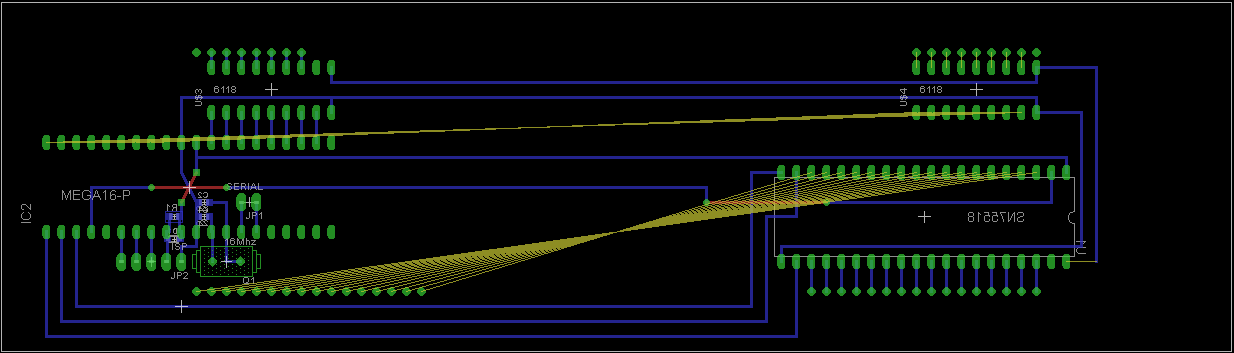 and it seems I need to make 2 boards because I can only get 160mm x 100mm perfboards, and it will be just long enough to fit all VFD pins, but space left over that is only couple holes. Also I must use flat cable to fit all connections between display and driver IC, board cant handle all of then even without AVR and other wires. Also powersupply is still open, I can easily get 5V but 45V and AC for filament is small problem I need to get over with. I tested display with variable power supply, but 26 V were barely enough to lit segments.
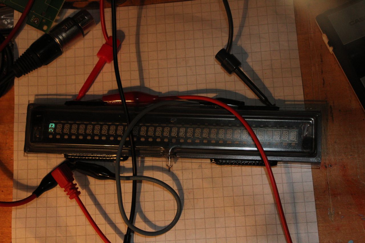
02.09.13 15:10 Edit :
I found out that my #define F_CPU had one zero missing, and that meant 1.6Mhz frequency when hardware were actually runing 16Mhz, no wonder why serial communication did not want work. I must test it again and report if it is now working.
Hi Henri! Did you do anything else with this VFD Display and the SN75518 with Arduino? Thanks
Hi friend! I have this Display here: https://www.ebay.com/itm/Samsung-Temp-Cook-Time-SVM-06ME08-Vacuum-Fluroescent-Display-Tube-Part-M64-/371194582804?_ul=BR and I would like to use it with a SN75518 and Arduino to make a Clock. The pins, from right to left are: 1-2, 3.3 volts Filaments; 3-16, Segments; pin 17 not connected; 18-23, Grids; 24-25, GND Filaments. I would like to know the sequence of the SN75518 pins to turn on the VFD Display and how to declare in the Arduino sketch;
The sketch ‘By Kesselwagen’ is at the bottom of this page: https://www.instructables.com/id/Arduino-VFD-Display-Clock-Tutorial-A-Guide-To-VFD-/ (VFD7Segment.ino)
My early thanks
Can I replace the 6118 with a Boost Converter like the XL6009?
Sorry, I had not seen your answer; thank you very much for the comment
Hi friend! It was not clear to me what Circuit Driver and what components you used. I have a VFD with 10 digits and I would like to plug it into the Arduino. Can not connect it directly to the Arduino pins? Thanks
I used 6118 high voltage buffers and SN75518 high voltage shift register for driving display. Sadly you can not drive VFD directly from Arduino. VFDs are kind of vacuum tubes, and they need 15V to 60V on grids and anodes to activate them. Arduino can only provide 5V which is not enough to light up segments. You must use either high voltage buffer ICs or discrete transistors between display and Arduino. VF displays also need a couple volts of AC for heater filament which must be center tapped and coupled to negative side of anode power supply.
Noritake Itron has great guide how to use and drive vacuum fluorescent displays: https://www.noritake-elec.com/technology/general-technical-information/vfd-operation