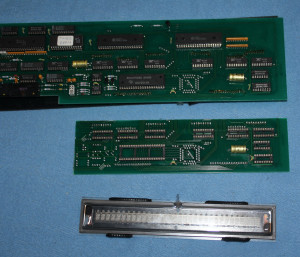
 I dug out my old VFD display project. This time I got some text showing up and prototype ready to be even bolted in some enclosure. I started with sawing piece of from original display controller as I didn’t bother to make PCB to house VFD screen, and all needed IC:s and connections were already there. Removing piece from 2mm fiberglass board is not easy task when your only tools are couple of hobby knives. But sawing boards with hacksaw would have caused more nasty fiberglass mess.
  It could be prettier. But edges are somewhat straight and it could be worse, I could have destroyed whole board. If I end up using this board as final display, I might sand edges more down, and maybe remove unneeded traces from edges.
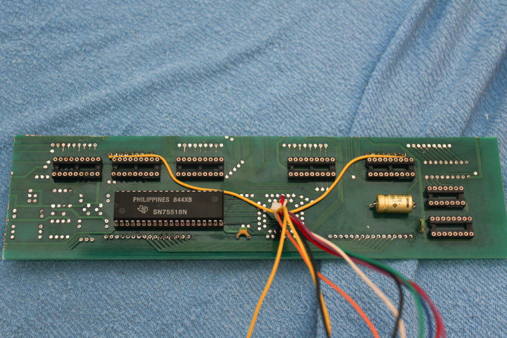 Wires for SN75518N shift register/buffer and power lines. Yellow wires for +8V filament, orange for +45V acceleration voltage and red for +5V logic. Have I mentioned that VFDs work like CRTs? Accelerated electrons from filament collide with phosphor exiting it to emit light, cool technology.
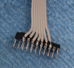
I forgot to attach segment wires before soldering display back in to the board, whoops… Kludging wires straight to IC pins works too, this is just prototype you know.
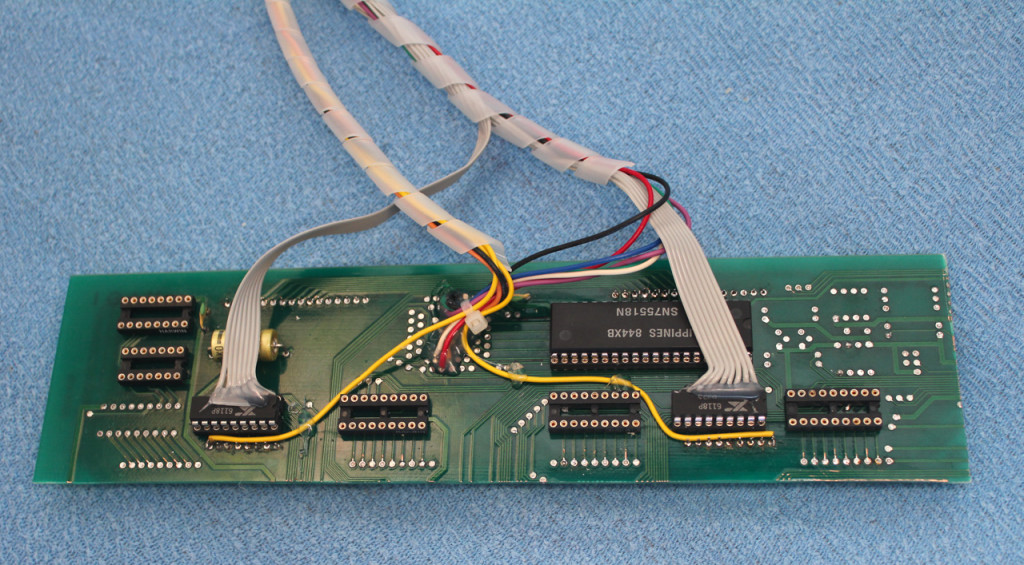 Anyways whole board is mess. Hot glued wires and unpopulated IC sockets. Traces that lead nowhere and have open unshielded edges.
I hope I find way to get PCB this size made to final version. Even tough I’m hacker, this is too hacked together to please me. Whole circuitry needed to operate display would fit to 2 sided board, even if home-made (though non-plated trough holes would be problematic).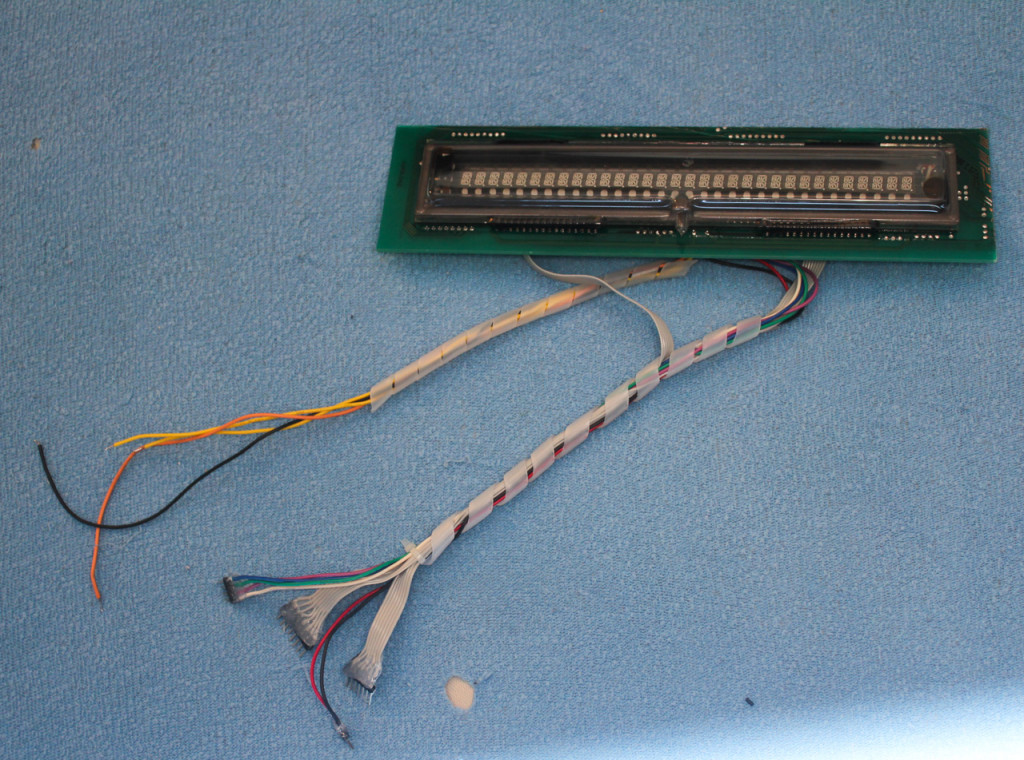 Module ready to be tested
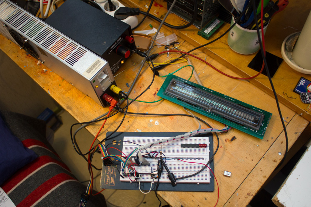 Work desk as messy as always. I had to use all power supplies I had around, to generate needed voltages. I didn’t have supply that would give needed +40V, so 12V and 28V supplies were used together. As some of you could recognize, hat long one is from PS/2 computer fitted with banana jacks, ideal for work like this. Black one is old battery charger that got new life as adjustable 8-28V power supply. It has descent voltage regulator and transistor and can supply peak current of 4A with 2A self resetting slow fuse.
You can see WIP code here. It can show text that is wrote on textBuffer with memmove. Basic multiplexing and display driving works, nothing else. Next I need to implement working USART driver that does not hog all cpu cycles and does not interrupt display refresh. Then just get all control charters to work, so it can be used as 32×1 serial terminal.
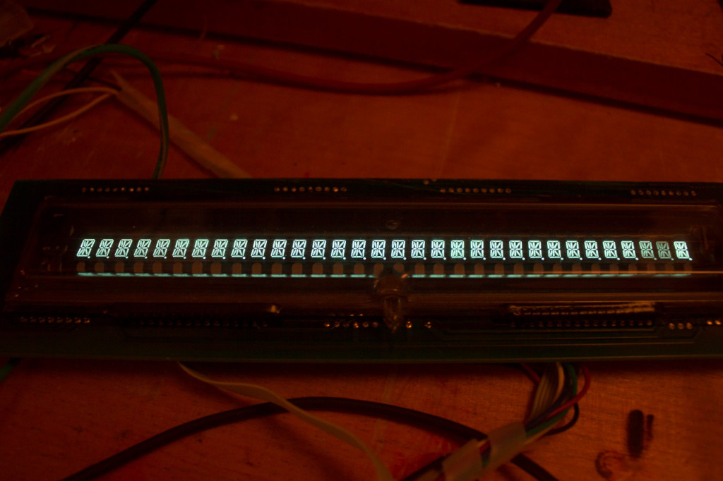
Display has still life hours left, only some very slight burn in can noticed. Dimming on 2 digits on right end should not be confused as burn, it is due shutter speed I used. Flickering is not visible with naked eye, but camera sees it better. Persistence of vision is crucial, without it nearly all displays would be not possible. Clever “defect” of human brain.![]()
![]()

Some charter examples. Font is made by me with wuffe’s kukkafont generator. I could not get all small letters and special charters to look good. This is limit of display as it is only 14 segment one. With 16 segment displays that have top and bottom segment in 2 parts, better looking charters are possible. Capital letters and numbers look perfect though. I really love color of display, it is not green nor blue. Second best display type after gas discharge ones! 
Looking good, I can’t wait getting display to use. This would make awesome way to show titles of new emails and RSS feeds. Small embedded ARM computer could get titles from gmail and feedly (the best RSS online feed reader out there with very good desktop and mobile client options). Writing software to do that is still out of my league, but in couple of years possible I think. Using available APIs to login and get new messages and feeds with simple java client could not be that hard, could it?
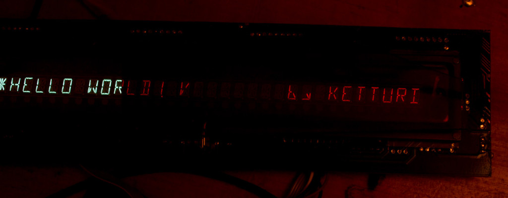
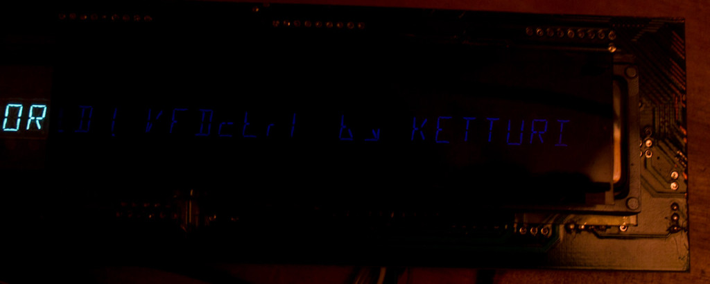
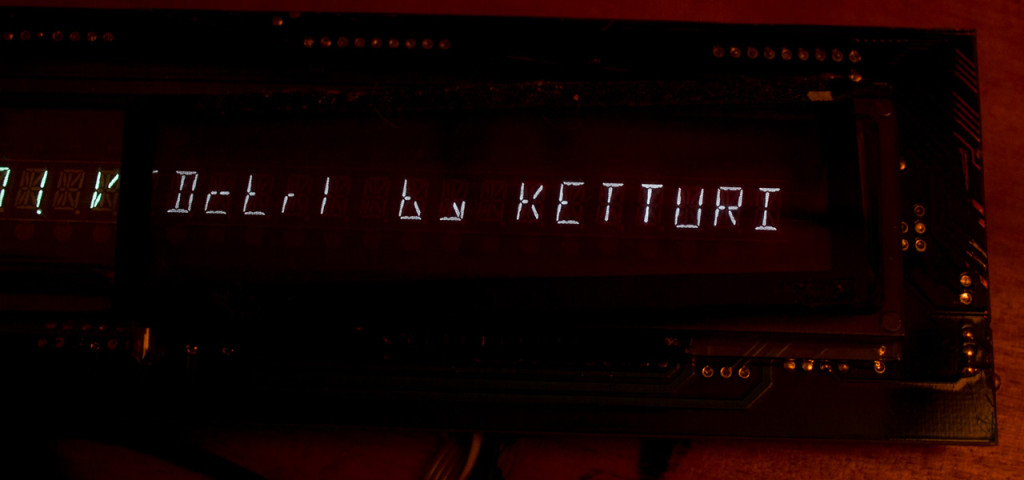 Tested some filters in front of display, but red and deep purple(more likely blue) made display far too dim, and light purple does not suit my preferences even though it makes VFD segment show as white.
 Green it is, just look how beautiful it looks. This outweighs all LCD’s and LED displays out there. Who cares about detailed font or colors, it is just old style that delight me.
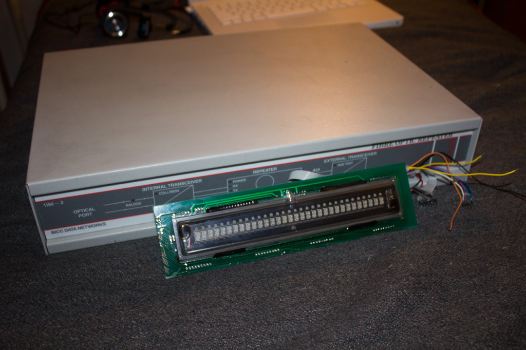 And then there is question how I should encase this display. Originally I tough using that old fiberoptic transceiver housing, but it is little too wide and deep to use in this project. But one idea I had that I would make small ITX HTPC into that case, and use display as it’s status display to describe playing media, and other information, but maybe not. I would have no use for it, and I want this display next to my bed with my nixie alarm clock. If could I somehow connect them together, it could show weather information and messages and new that have come during night when wake-up alarm goes off. But this is just brainstorming and ideation, I actually have no idea what final form of this display will be.
Stay tuned for more updates!

Hi! Did you finish your VFD code? The page for the “WIP code” is giving an error. If so, could you send it to my email? Thank you