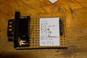
 Sometimes I find myself in need of interface some old tech that uses legacy RS232 interface. The thing is today’s computers and other smart logics do not have real TIA-232 compliant serial ports. The RS232 standard uses voltage levels that range from ±3V to ±15V, and space between -3V and +3V is defined as not valid. And a logic 1 is transmitted as negative voltage.
Even though use of RS232 ports are seldom use anymore, an asynchronous serial communication is not dead. Many embedded systems use it as debug interface. Also some devices still use it as communication interface, even if physical layer is implemented with USB or Bluetooth. As said before, RS232 is not physically compliant with UARTs in modern integrated circuits. Many times UART voltage levels range from +5v to 1.8V, where positive voltage is logic 1 and 0V is logic 0. Connecting UART straight to RS232 connector is very bad idea and should never be done, as circuit using lower one rail supply may and will be damaged. Even using resistors and diodes to translate voltage levels may not work, as not all rs232 devices recognize 0V as logic 1. So external voltage level shifter/converter/translator must be used.
I had ST232AC on my IC junk box. It is pin to pin compatible STMicroelectronics improved version of legendary MAX232, Maxims dual transmitter/receiver RS232 to TTL converter. It has internal charge pump and inverter, so it works with just one supply voltage, +5V (I believe it could also work with 3.3V). This kind of ICs are very popular and are used by many hobbyist to connect their microcontroller projects to computers serial ports. I myself have different need, I want interface with older accessory devices, and connect them to microcontrollers, or to FTDI USB to UART adapter.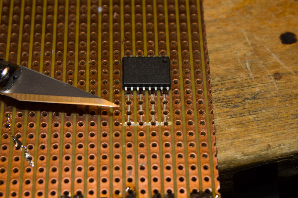 ST232 I had is in SO-16 package, and I don’t have break out boards on my hand, so bit improvisation with x-acto knife and veroboard.
 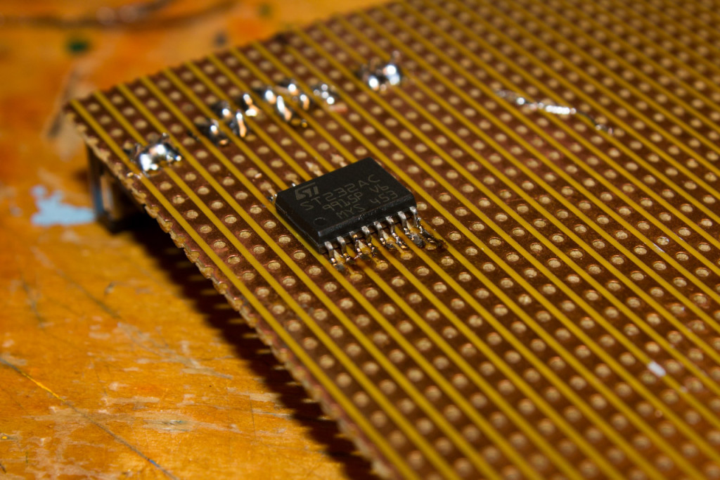 And soldered down. Fitting DE-9 connector to veroboard was also little troublesome, these connectors do not fit in normal squarish layout of perforated boars, and bending pins & carving holes to oval is needed.
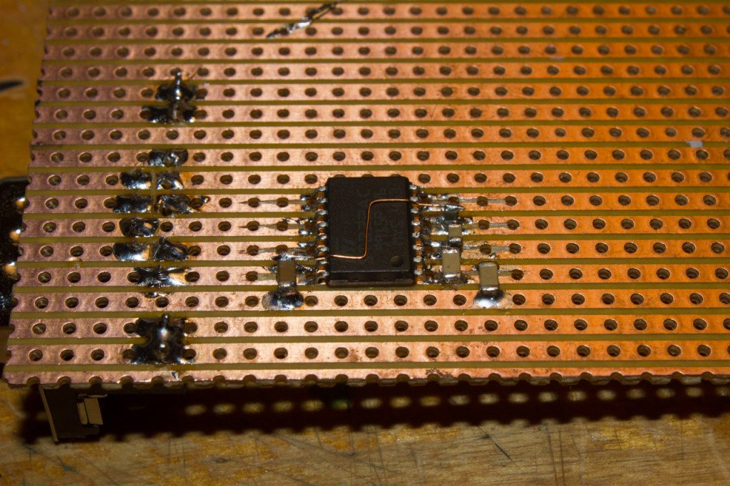 4 SMD capacitors for charge pumps and one for supply voltage filtering. Notice wire going from tombstoned capacitor to ground.
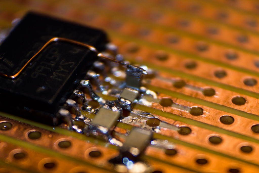
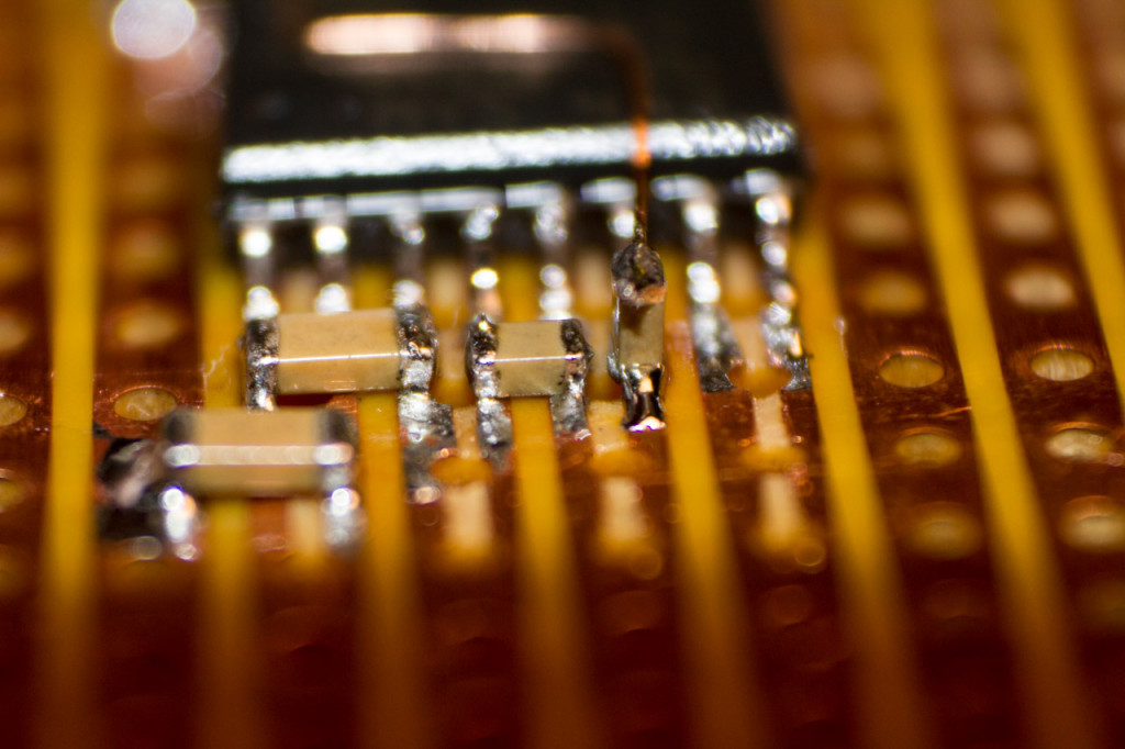
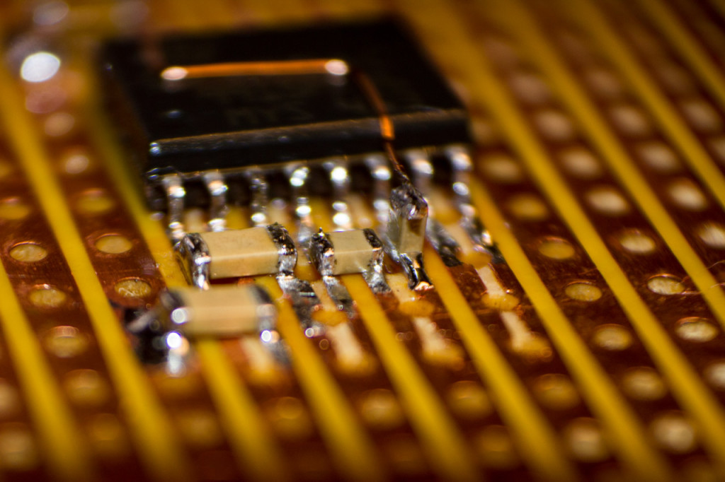
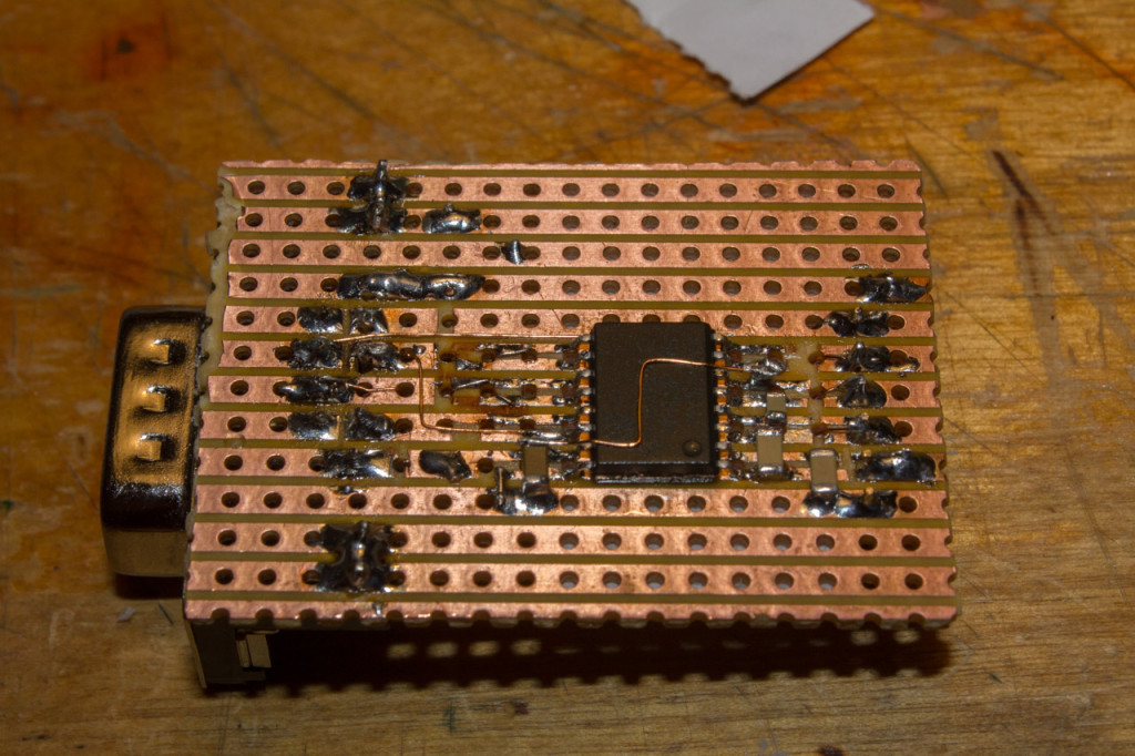 Forgot to take more pictures between building steps. Ready circuit that works perfectly. Soldering is bit messy, I should have cleaned the veroboard as it felt bit dirty/corroded when soldering(solder not sticking).
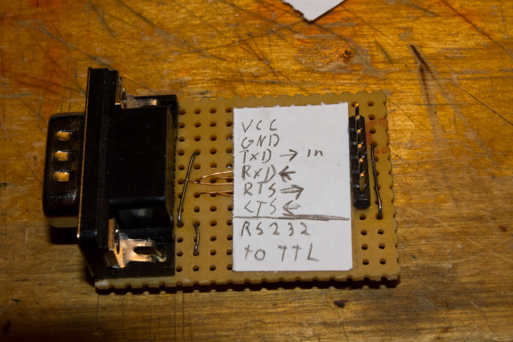
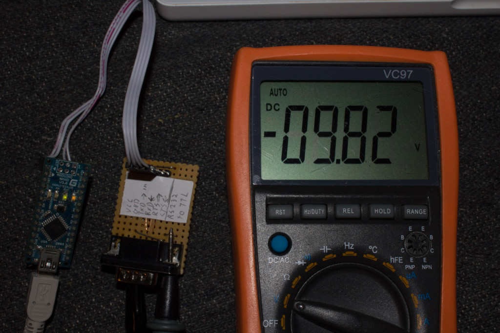 It works! ST232 is generating ±9.80V from 5v when lines not loaded. It takes under 10mA and works perfectly with arduino and other development tools! I left DCD&RI and DTR&DSR pairs unconnected, as they are used not as often as RTS&CTS (hardware flow control), this can be used with any 3 or 5-wire async. serial device. If shomehow other lines are needed, they can be wired to permanently low or high, but most devices should work without these.
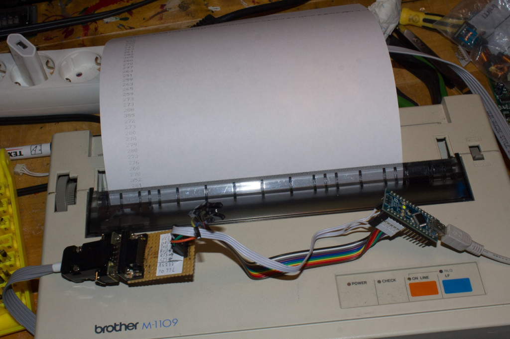 Arduino printing numbers (first example from IDE or so) trough RS232 interface build in old dot matrix printer. RTS was pulled low to get printer accept data in. Printer is mostly on way device, if software flow control and error signals are ignored, this printer just toggles CTS to tell that it is online, and sends device control charter if xon/xoff is enabled from dip switch settings.
