Yesterday I found an old calculator from e-waste center, which caught my attention. At first glance I knew that this was not ordinary VFD or LED display desktop calculator. So I stuffed it into my bag and scurried back to home with my precious find. At home I plugged the calculator into the wall socket, which I probably shouldn’t have done. Of course it did not work. But no worries, what could I could not fix?
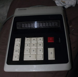 This calculator was probably dead long before I got it, but still it is newer good idea to power old equipment without looking inside and slowly rising voltage, e.g. trough 60W lightbulb. Anyway, I carefully measured operating voltages. Voltage for logic circuit were about normal, but one for display was showing unbelievable values. I don’t remember anymore exact numbers, but like dozens ac volts. Bridge rectifier was also running burning hot. It had 1 short and 1 open diode.
I did not have replacement rectifier on hand, but I made equivalent from individual diodes. Later this proved to be poor choice. After changing rectifier voltage was 100DC, which I thought to be correct voltage for display. But still new diodes were warming up fast and I
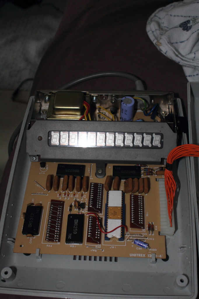 started to cut parts out from circuit. Unsoldered both of display driving ICs, then severed whole trace feeding them. Still same problem. So I removed resistors which were regulating and voltage for display. No change. I was frustrated and had no idea what to do next. Diodes were melting solder from their leads. I replaces 22µF 250V electrolyte cap because usually they boil dry if they get AC current trough them and may also short themselves. Got new capacitor, still huge current drainage. Next step: isolate the problem.
 Here is circuit diagram from parts I changed or removed. All resistors were ok, and capacitors were spot-on. Even without them current draw was 140mAAC. Even with only rectifier and new C1, damn weird. After some thinking I decided to change rectifier again, even though all diodes measured ~0.500V. With new proper diode bridge, I got 200VDC!. A miracle. Likely I had chosen 1 diode which had not enough high break down voltage and went short when full circuit voltage were applied. There us also chance it was zener diode which are difficult to identify. Anyway, I got it working, after soldering all components back and cleaning flux residue etc. Whew <.<
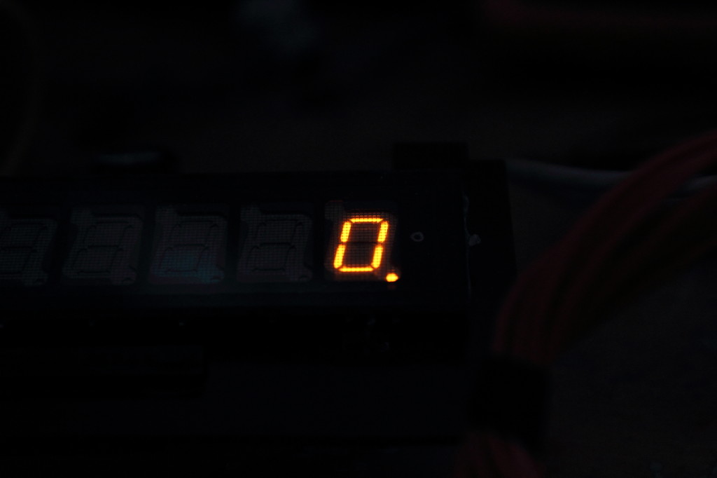
After whole terrible tinkering and getting fingers burned and once shocked from some weird charge(I’m sure I drained every cap), I got nice orange glow from display \o/. Then rebuilding calculator back to one piece. Original mains side was dangerous and poorly made. Little clearances and many solder joints, not good. I removed all original parts, installed new fuse holder, joined wires and covered all exposed parts with heatshrink.
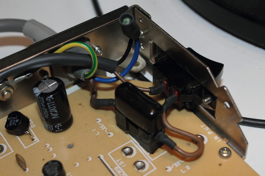 Not fulfilling every standard and regulations, but still better than before, i think.
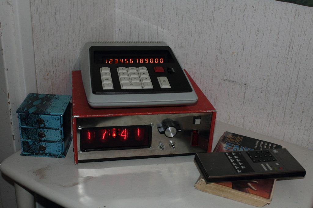 Lovely retro calculator that mixes nice with my clock. All pictures here.
Oh, and the lesson, newer trust yourself, check things twice, even if you are sure. Saves much effort, pain and resources.

Hi
Nice work, thanks
I have the same calc to repair. Little confused with the fuse: is it 100ma?