I had boring day, and was too lazy to do school works, so what else I could do but electronics? For next project I need power supply and due to poor efficiency of linear regulators, I choose to make an another switching regulator.
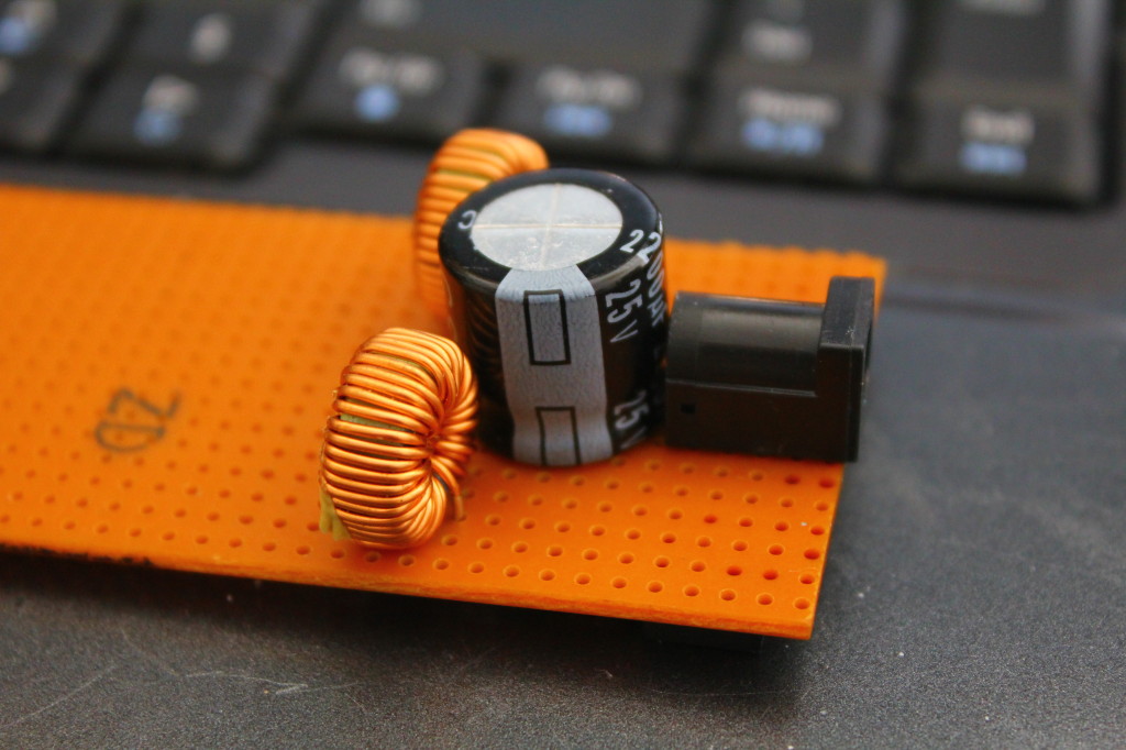
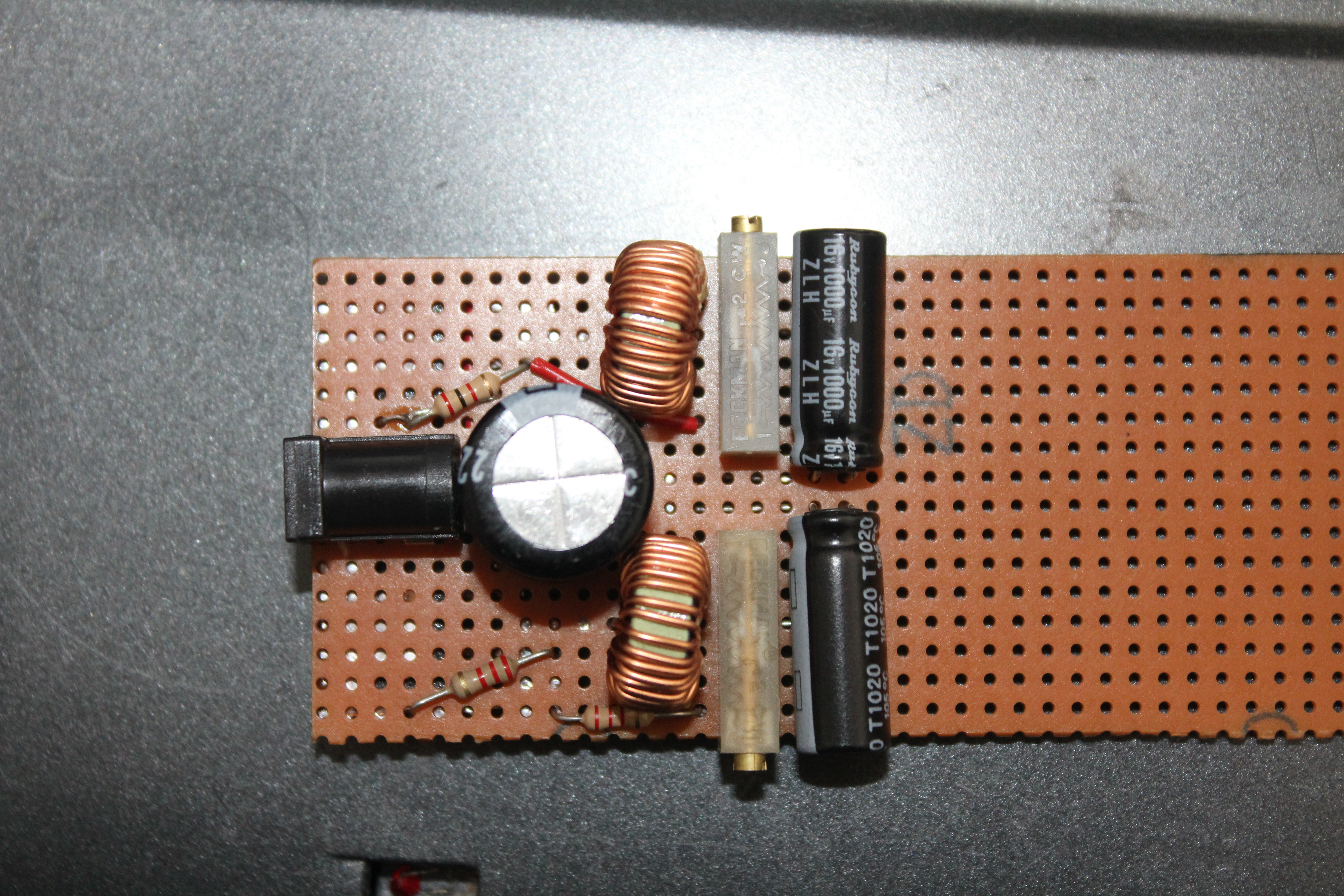
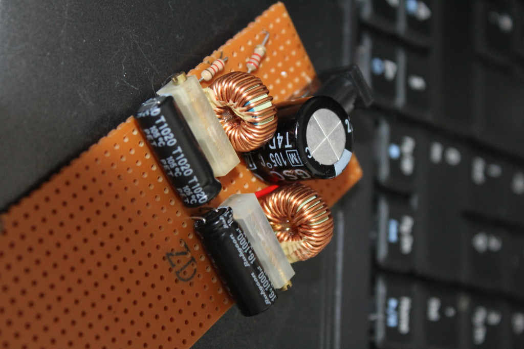
 And there is the blurry picture. Similar construction to the nixie clock’s power supply, but this time double. Inductors are also different, because I couldn’t find similar cylinder shaped coils. Those arent 47µH like ones in datasheet, but should do the job.
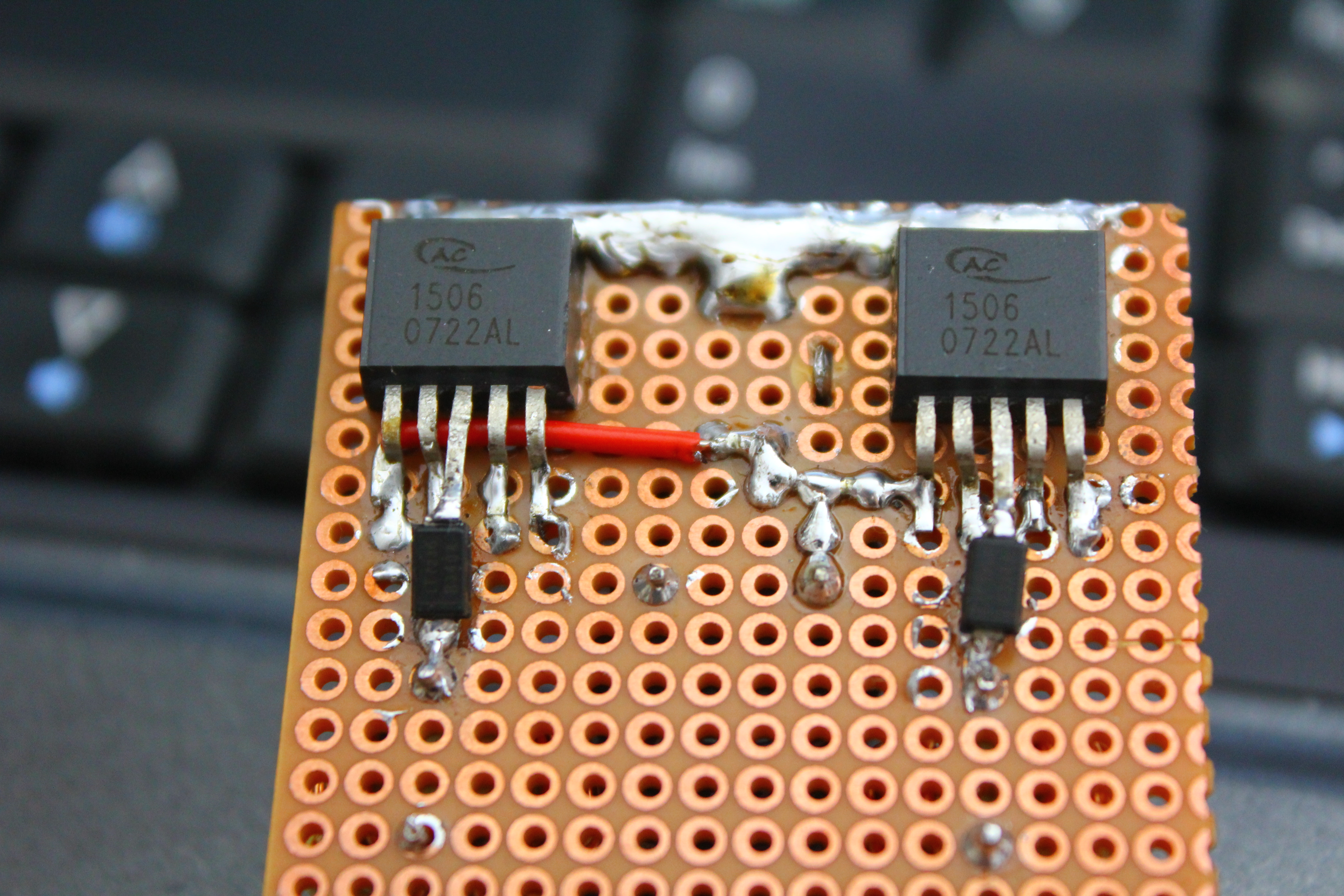
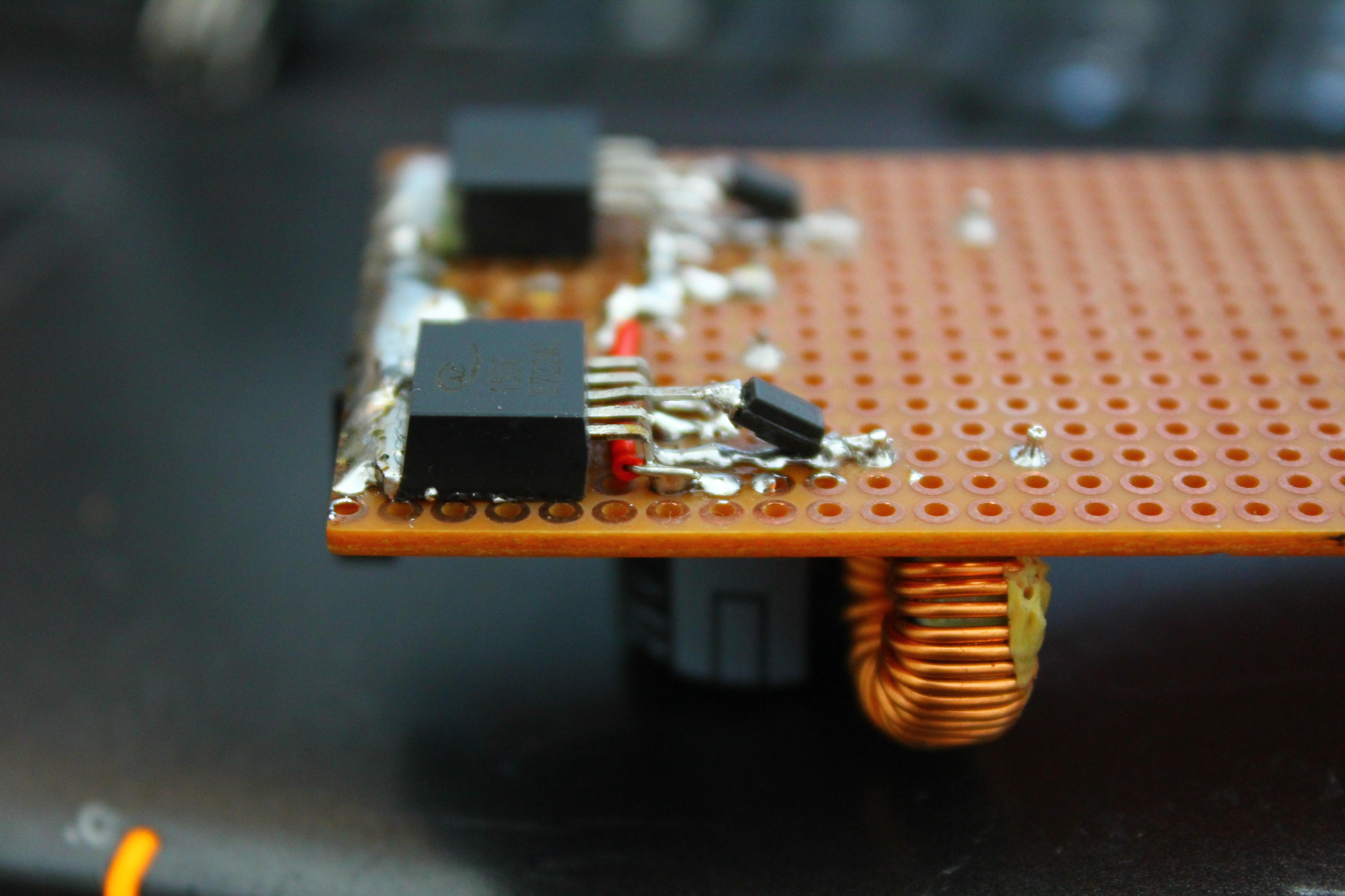
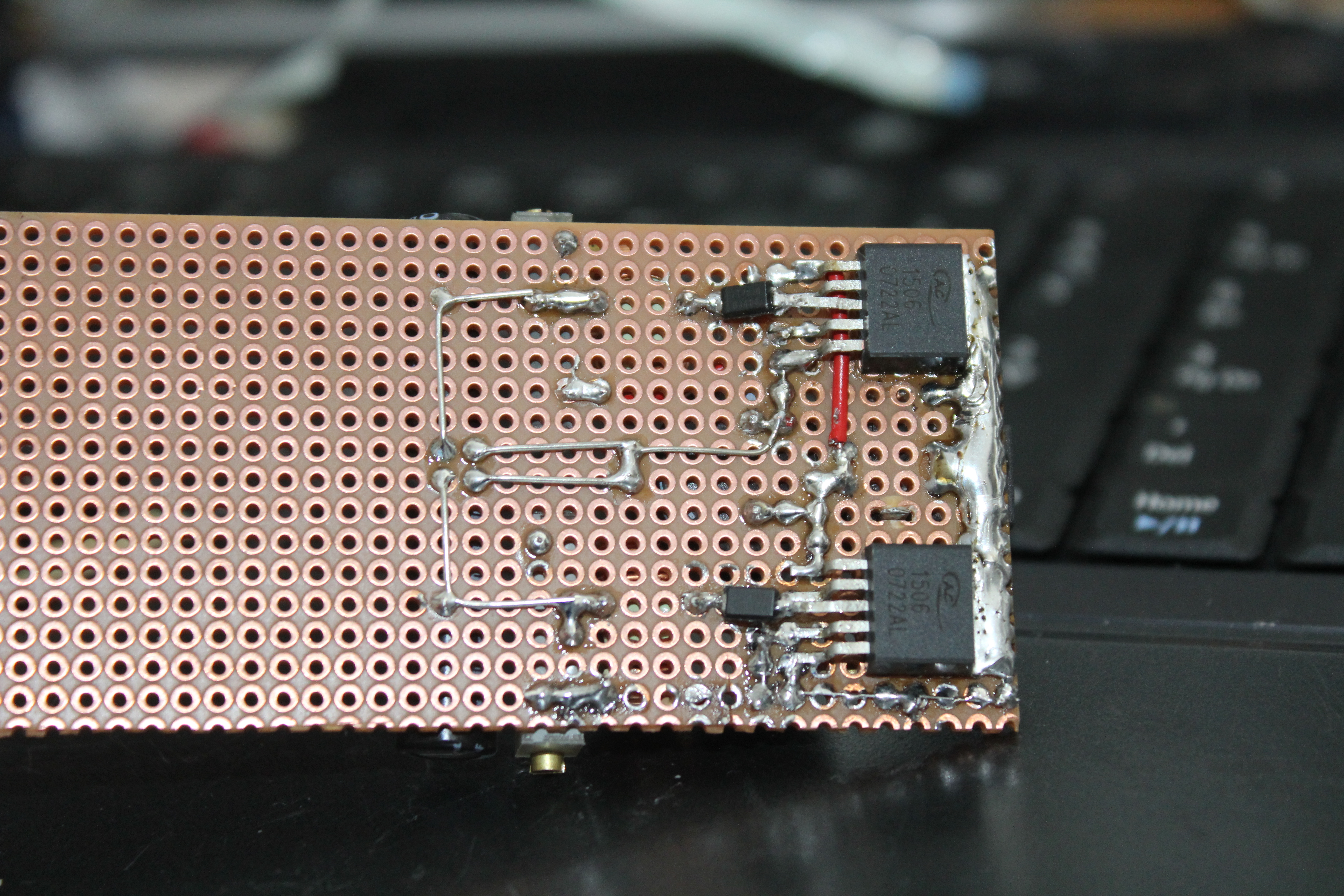
And not so nice soldering. Lifting middle pin and little bending 2 legs those TO263 packages fits perfectly to dot board. Big clump of solder is acting like poor heatsink.
 Ah, the warmth of copper and FR-2 <3
 Well it gives steady 9v and 5v, looks nice (if bottom side is left to darkness) and have better performance than 78** regulators.
And now, the 5 point question, for what it will be used for? Here comes the hint: MOS SID